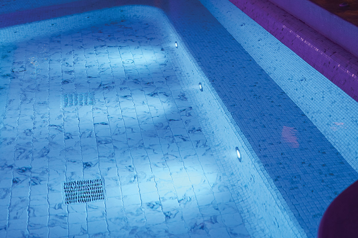
Section 68 of the Canadian Electrical Code, Part I, applies to electrical installations and electrical equipment in or adjacent to pools. In this section of the code, a pool is deemed to include:
1. permanently installed and storable swimming pools;
2. hydromassage bathtubs;
3. spas and hot tubs;
4. wading pools;
5. baptismal pools; and
6. decorative pools.
When an electrical product is submerged in the water of a pool, some of the current that is drawn to power the equipment will enter the water external to the equipment as leakage current and flow to ground via the pool walls and non-current-carrying metal parts of pool equipment that are bonded to the ground. The amount of leakage current is equal to the difference between total current drawn by the product and the current returning to the neutral of the supply circuit.

Figure 1. Current density test probe
When a person is immersed in pool water at or near the location of a submerged electrical product such as a luminaire, a portion of the leakage current will pass through that person’s body before flowing to ground. The portion of leakage current that enters a person’s body is known as body current.
A luminaire intended for use in a pool must be constructed so that body current caused by the luminaire, when it is submerged and energized, does not present a shock hazard to any person who is immersed in the pool water at or near the location of the luminaire.
In situations where a person is not immersed in water, it is not difficult to determine total body current when the person is in contact with an electrical product. The situation is different, however, when a person is immersed in a conductive medium such as pool water.
It has been found that some methods used to determine the amount of leakage current from a luminaire only measure the total leakage current that enters the pool water, without indicating what portion of that current might enter a person’s body. This approach is considered unrealistic for use as a compliance test for submersible equipment.
Another factor not taken into account by traditional methods used for measuring leakage current is that a person’s body affects the total resistance of the current path taken by the leakage current. The total resistance of the current path depends upon the resistivity of the pool water and the impedance of a person’s body when immersed in that water.
While a person is immersed in a pool, the water forms an infinite series of conductive paths in parallel with the person’s body.
The total current that flows in a person’s body is affected by the area of the body and the electric field in the water.
For the purpose of determining the amount of current that flows in the body, the term “current density” is used. It is a measure of current flow per unit area and is expressed in amps/cm².
A number of articles1have been written regarding different physiological effects of electric current on the human body. Among these effects, in the order of least to most serious are perception, reaction, let-go, stoppage of breathing, ventricular fibrillation of the heart, electric burns, and paralysis. Of these physiological effects, electric burns, let-go and ventricular fibrillation are considered to be most critical.
A current flowing in a human body can heat body tissues sufficiently to cause serious burns. However, no specific values of current that cause electric burns to people have been established.
“Let-go” is a phenomenon in which a person’s ability to release his/her grip on a current-carrying part depends upon the extent of that person’s involuntary muscle contractions caused by the flow of body current. When the current of the current-carrying part is further increased, ventricular fibrillation will occur.
Ventricular fibrillation occurs when contractions of the heart cause heart action to become uncoordinated and asynchronous, and the heart becomes unable to function any longer as a pump.
When a person is immersed in a pool, the area of the person’s body considered most critical is the chest-heart area.
The current density limit for this area should be determined based on the threshold of ventricular fibrillation of a two-year-old child. The limit for a 60 hertz sinusoidal current as determined by A. Smoot and C.A. Bental²is 30 A/cm². The limit also includes some safety factors.
To accurately measure the current density of water in a pool in which energized electrical products are submerged, CSA International recognized that a special test probe is required.
According to Ohm’s Law, for a constant source voltage a change in load resistance will change the current flowing in the load. This principle also applies to the current density in pool water. The total resistance will change if an object having a higher or lower resistance is submerged in pool water having uniform resistivity.
In Bulletin of Research No. 60, A. Smoot and C.A. Bental2 describe the development of a shock hazard test procedure for underwater swimming pool luminaires and the basis parameters for constructing an experimental current density
test probe.

Figure 2. Equipment for calibrating current density test probe
Recognizing the importance of the experimental test probe and with the expectation that this technology could be put into practice, CSA proceeded to build further the existing research work that had already been done. A current density test probe was developed, utilizing two 20 mm diameter by 0.5 mm thick copper discs (see figure 1 for details).
The copper disc electrodes were mechanically attached and sealed to an 8 cm long teflon body. A hole was made through the centre of the teflon body along its longitudinal axis for the full length of 8 cm. A 4.2 mm diameter plastic tube and sleeve were inserted through a second hole drilled at the centre of the teflon body perpendicular to the longitudinal axis to form a water-tight joint and inverted “T”-shaped wiring raceway. The plastic tube may be of any length that is suitable for conducting a current density test.
A length of 45 cm was found to be sufficient.
Two insulated No. 26 AWG stranded copper wires were threaded through the plastic tube and teflon body and connected to two bronze threaded rods, each rod being soldered to one of the copper disc electrodes.
The two leads were twisted together to reduce any mutual electromagnetic field generated by the flow of current. The two copper disc electrodes function to detect any minute current flow when the test probe is immersed in the water of
a pool.
In order to measure the current density in pool water, the test probe should be electrically invisible in the water. To be invisible the probe must have the same resistance as the volume of water it displaces. Therefore, the current in the pool water would flow through the probe in the same manner as it would have through the water the probe has displaced. Any current which flows in the main body of water surrounding the probe would not be diverted away from or attracted to the probe. To achieve “invisibility” the probe should be placed such that its axis is oriented orthogonal to voltage gradient in the direction of current flow in the water surrounding
the probe.
Since the resistance of the test probe, as constructed, may not match the resistivity of the pool water in the majority of installed pools, an external resistor is required to be connected across the probe leads. The resistivity of pool water normally ranges from 22 ohm-cm for sea water pools to 300 ohm-cm for treated fresh water pools.
To calibrate the test probe for pool water with a specific resistivity as may be prescribed by a safety standard, the following method
was used.
The work was conducted in an area free of radio interference.
The equipment for calibrating the test probe consisted of a uniform current density calibration glass tank, two 24 cm x 29.5 cm stainless steel plates mounted on the opposite ends of the tank, and a plexiglass plate with two electric field pick-up electrodes of 1.4 mm diameter stainless steel mounted 9 cm apart. The equipment is illustrated in figure 2.
The tank was then filled with water having specific resistivity. For example, 300 ohm-cm saline water was used for testing equipment submerged in fresh water pools.
A plexiglass plate was mounted on top of the tank, so that the two electric field pick-up electrodes were submerged in the test
solution water.
An ac supply was connected to the leads of the stainless steel plates and the voltage was gradually increased so that the potential across the electric field pick-up electrodes was about 65 mV and the current through the tank was adequately maintained at a constant value.
The test probe was submerged in the test solution and positioned between the electric field pick-up electrodes with its axis parallel to the tank main axis.
An external resistor was connected to the leads of the test probe and then adjusted until the test probe could be moved through the space of the electrical field pick-up electrode without causing a change in reading in voltage when the test probe was present or absent. In the investigation conducted by CSA, an external resistor of 650 ohms as determined by calculation was required to make the test probe invisible in a test solution having a resistivity of 300 ohm-cm.
To measure the current density generated by submersible electrical equipment such as luminaires, while submerged in a saline solution having the required resistivity, the following method is used.

Figure 3. Current density test probe for measuring current density in a solution
The submersible electrical equipment is placed in the saline solution and rated voltage is applied to the equipment.
A test probe that has been calibrated in a saline solution having identical resistivity is used. A high internal impedance mili-volt voltmeter is connected across the two leads of the test probe (see figure 3).
The test probe is moved around as closely as possible to the luminaire. Maximum voltage drop across the leads of the test probe, as indicated by the voltmeter in figure 3, is recorded. The maximum voltage drop (Vm) in millivolts is recorded when the axis of the test probe is aligned orthogonal to voltage gradient in the test solution surrounding the probe.
Current density, Id, expressed in A/cm² is defined as:
Id = Vm(A)
Rpx Ap
Where:
Vmis the maximum voltage drop in volts across the leads of the
test probe.
Rpis the total resistance in ohms of test solution displaced by the current density test probe.
Apis the area in cm² of the electrode disc of the test probe.
Equation (A) can be simplified as follows for ease of calculation of the current density using the maximum voltage drop measured.
According to Ohm’s Law:
Vm= I x Rp(B)
Where:
“I” is the total current in amperes that flows through the volume of the solution the test probe displaces.
However:
I = Idx Ap(C)
By combining Equations (B) and (C), Vm can be expressed in terms of Id as follows:
Vm= Idx Apx Rp(D)
However, Rp, the total resistance of test solution displaced by the test probe is defined as:
Rp= Rwx Lp(E)
Ap
Where:
Rwis the resistivity of water in ohm-cm.
Lpis the length of the test probe in cm.
Substituting Rpin Equation (D) for Rpin Equation (E):
Vm= Idx Rwx Lp(F)
Therefore,
Id= Vm(G)
Rwx Lp
It is obvious from Equation (G) that the current density (Id), is independent of the area of the test probe (Ap), even though the variable Apappears in Equation (A).
Equation (G) can be further simplified for ease of calculating current density of any saline solution with known resistivity, given the length of the test probe is also known.
As an example, a test solution having resistivity of 300 ohm-cm and a test probe shown as Figure 1, Equation (G) can be rewritten as:
Id= Vm(H)
2400
Equation (H) provides a simple way to calculate the current density in a solution having a resistivity of 300 ohm-cm, for different types of submersible electrical products, when the test probe shown in figure 1 is used.
It must be emphasized that the measuring method described so far is intended to measure the current density in a solution as a result of the submersion of an electrical product with or without the failure of a sealing means.
The same current density may not be experienced by a human body because of the skin resistance, tissue resistance and configuration of the body.
The combined resistance of these factors could possibly reduce the current density that is experienced by the human body to as low as five percent of the current density of the test solution.
However, taking the current density in the test solution as it is, without applying the correction factor for the current density experienced by a human body, is considered to be the worst-case scenario.
This approach to evaluating a product under the worst-case scenario is consistent with the generally accepted practice of recognized testing laboratories such as CSA, and the test probe described in this article does provide a practical means to measure the maximum possible current density that could be experienced by a human body submersed in pool water.
1. “Development of test equipment and methods for measuring potentially lethal and otherwise damaging current levels,” U.S. Consumer Product Safety Commission/Underwriters Laboratories Inc., pp. 2-1–2-4, May 1981.
2. A. Smoot and C.A. Bentel, “Development of a shock hazard test procedure for underwater swimming pool lighting fixtures,” Underwriters’ Laboratories Inc., Bullet of Research No. 60, pp 41–44, November 1971.


Find Us on Socials