The 2002 National Electrical Code brings changes to the industry. Adopting provisions to keep up with advancing technology and recognizing that many existing safety rules have to be modified to address specific situations require reexamination of existing Code rules on a regular basis. The Code development process needs the participation of experts in the field as well as general users of the document to identify and implement necessary changes. That process has been followed for the 2002 edition of the NEC, and the challenge now present is for users to become familiar with the new and revised safety rules. The International Association of Electrical Inspectors and the National Fire Protection Association have combined their efforts to provide a comprehensive coverage of approximately 400 changes made in the 2002 NEC. The 2002 NEC Analysis of the Changes has been developed and is available through both organizations to help Code users learn of changes made in the Code and how it will affect them and their work.
The 480-page 2002 NEC Analysis of the Changes book is designed to provide an easily understood description of each covered change and includes a drawing or photo to compliment the written description. The four-color drawings and photos are not only intended to be pleasing to the eye, but also are designed to aid in understanding the changes. Drawings are used to provide details in graphic form to help explain aspects of changes that would require an extensive description in wording. Considerable effort has been devoted to give as much coverage of changes as possible in a concise form and to provide information that helps the user understand the changes. The following sample changes are included to show the type of material included in the 2002 NEC Analysis of the Changes.
110.15 High-Leg Marking [See figure 1]
Type of Change: New
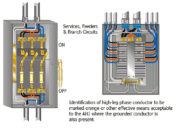
Figure 1. 110.15 High-Leg Marking
Summary of the Change:
A new provision covering the identification of the high-leg on 4-wire, delta-connected systems has been added to Article 110.
Code Language:110.15 High-Leg Marking. On a 4-wire, delta-connected system where the midpoint of one phase winding is grounded to supply lighting and similar loads, the conductor or busbar having the higher phase voltage to ground shall be durably and permanently marked by an outer finish that is orange in color, or by other effective means. Such identification shall be placed at each point on the system where a connection is made if the grounded conductor is also present.
Analysis of the Change:The addition of this provision in Article 110 makes it a general requirement for the marking of the conductor having the higher voltage to ground on 4-wire, delta-connected systems. Specific rules relating to branch circuits, feeders, and services for switchboards and panelboards are covered in 210.4(D), 215.8, 230.56, and 408.3(E). Adding this provision in Article 110 will cover marking of the high-leg conductor in locations not covered by existing rules in other articles. In conjunction with this action, the 1999 wording in 384.3(E) on high-leg marking has been relocated as 400.3(E), and a new fine print note has been added to reference 110.15.
110.26 Spaces About Electrical Equipment [See figure 2]
110.26(C) Entrance to Working Space
Type of Change:Revision
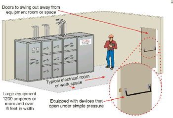
Figure 2. 110.26 Spaces About Electrical Equipment
Summary of the Change:
The title of 110.26(C) has been revised, the exceptions have been amended and located as part of the standard text, and the section has been restructured. The wording “Access and” has been removed from the title and it will now read “Entrance to Working Space.” A new sentence has been added to the newly designated “”(2) Large Equipment”” to read, “Where the entrance has a personnel door(s), the door(s) shall open in the direction of egress and be equipped with panic bars, pressure plates, or other devices that are normally latched but open under simple pressure.”
Code Language:110.26(C) Entrance to Working Space.
(1) Minimum Required.At least one entrance of sufficient area shall be provided to give access to working space about electrical equipment.
(2) Large Equipment.For equipment rated 1200 amperes or more and over 1.8 m (6 ft) wide that contains overcurrent devices, switching devices, or control devices, there shall be one entrance to the required working space not less than 610 mm (24 in.) wide and 2.0 m (6 1/2 ft) high at each end of the working space. Where the entrance has a personnel door(s), the door(s) shall open in the direction of egress and be equipped with panic bars, pressure plates, or other devices that are normally latched but open under simple pressure.
A single entrance to the required working space shall be permitted where either of the conditions in 110.26(C)(2)(a) or (b) is met.
(a) Unobstructed Exit. Where the location permits a continuous and unobstructed way of exit travel, a single entrance to the working space shall be permitted.
(b) Extra Working Space. Where the depth of the working space is twice that required by 110.26(A)(1), a single entrance shall be permitted. It shall be located so that the distance from the equipment to the nearest edge of the entrance is not less than the minimum clear distance specified in Table 110.26(A)(1) for equipment operating at that voltage and in that condition.
Analysis of the Change: This change addresses the concern for the safety of people who work on energized equipment described in this section and their ability to exit through personnel doors in cases of emergency. The door opening devices are required to operate on simple pressure and will permit an injured worker to exit the area more easily than through a door having a conventional twist-type knob or handle. Workers with injured hands are likely to have difficulty in turning a door knob to open a door and that problem is further complicated if the door opens inward. This rule in conjunction with the new requirement in 110.16 of the 2002 NEC regarding warning of potential arc-flash hazards should contribute to safer working conditions.
250.54 Supplementary Grounding Electrodes[See figure 3]
Type of Change: Revision
Summary of the Change:
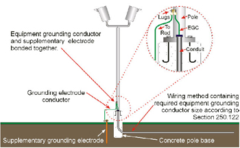
Figure 3. 250.54 Supplementary Grounding Electrodes
This section was revised to clarify the bonding rule for supplemental electrodes.
Code Language: 250.54 Supplementary Grounding Electrode. Supplementary grounding electrodes shall be permitted to be connected to the equipment grounding conductors specified in 250.118 and shall not be required to comply with the electrode bonding requirements of 250.50 or 250.53(C) or the resistance requirements of 250.56, but the earth shall not be used as the sole equipment grounding conductor.
Analysis of the Change: This revision provides clarification that supplementary grounding electrodes, where installed, are not required to be bonded to the grounding electrode system directly as indicated in 250.50. Supplementary electrodes are, however, required to be bonded to the equipment grounding conductor included in the branch circuit or feeders. An example of this use of the supplementary electrode is where an electrode is installed at a light pole base in a parking lot. The electrode in this case is required to be bonded to the equipment grounding conductor of the circuit, but a bonding jumper in accordance with 250.50 is not required to bond the supplementary electrode to the grounding electrode system for the service of the building or structure. This change does not affect the language in this section that indicates that the earth shall not be used as the sole equipment grounding conductor.
Type of Change: Revision
Summary of the Change: The first sentence of the main paragraph of 250.148 has been revised to address situations where equipment grounding conductors are spliced within a box or terminated on equipment within or supported by the box.
Code Language: 250.148 Continuity and Attachment of Equipment Grounding Conductors to Boxes. Where circuit conductors are spliced within a box, or terminated on equipment within or supported by a box, any separate equipment grounding conductors associated with those circuit conductors shall be spliced or joined within the box or to the box with devices suitable for the use. Connections depending solely on solder shall not be used. Splices shall be made in accordance with 110.14(B) except that insulation shall not be required. The arrangement of grounding connections shall be such that the disconnection or the removal of a receptacle, luminaire (fixture), or other device fed from the box will not interfere with or interrupt the grounding continuity.
Analysis of the Change: Metallic boxes and other enclosures are required to be grounded by the provisions of Article 250. The requirement in the 1999 NEC specified that an equipment grounding conductor pulled through an enclosure or box used as a pull box was required to be cut or tapped and connected to the box even though no similar requirement applies to conduit bodies used in the same manner. Where conductors pass through a box or conduit body and the box or conduit body is grounded by the metal raceway attached to it, the equipment grounding conductor is not required to be attached to the box or conduit body. Where metallic boxes or pull boxes are installed with nonmetallic raceway methods, equipment grounding conductors are required to be installed with the circuit conductors and the box or enclosure would be required to be grounded by other provisions in Article 250, specifically 250.80 or 250.86.
300.5 Underground Installations [See figure 4]
300.5(K) Directional Boring
Type of Change: New
Summary of the Change:
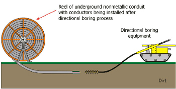
Figure 4. 300.5 Underground Installations
A new 300.5(K) has been added to cover cables or raceways installed underground by directional boring equipment.
Code Language:300.5(K) Directional Boring. Cables or raceways installed using directional boring equipment shall be approved for the purpose.
Analysis of the Change: This new rule addresses installations where continuous reel raceways or cables are installed utilizing directional boring equipment. The submitter indicated that both listed and non-listed raceways have been installed during the directional boring process and failures have occurred. The report cited instances where raceways were reduced in diameter and joints separated due to the pulling pressure. This new rule requires that raceways and cables be “”approved for the use”” but do not require “”listing.”” The emphasis of this provision is that raceways and cables installed through the use of this type of equipment must be suitable for the types of stresses and conditions encountered.
430.53 Several Motors or Loads on One Branch Circuit
430.53(D) Single Motor Taps [See figure 5]
Type of Change: New
Summary of the Change:
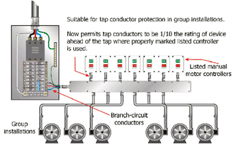
Figure 5. 430.53(D) Single Motor Taps
A new tap rule has been added to 430.53(D) as item (3) and covers conductors supplying specific manual motor controllers.
Code Language:430.53(D)(3).Conductors from the branch-circuit short-circuit and ground-fault protective device to a listed manual motor controller additionally marked “”Suitable for Tap Conductor Protection in Group Installations”” shall be permitted to have an ampacity not less than 1/10 the rating or setting of the branch-circuit short-circuit and ground-fault protective device. The conductors from the controller to the motor shall have an ampacity in accordance with 430.22. The conductors from the branch-circuit short-circuit and ground-fault protective device to the controller shall (1) be suitably protected from physical damage and enclosed either by an enclosed controller or by a raceway and shall be not more than 3 m (10 ft) long or (2) shall have an ampacity not less than that of the branch-circuit conductors.
Analysis of the Change:This change permits conductors sized not less than 1/10 the rating of the short-circuit and ground-fault protective device on their supply side to feed listed manual motor controllers that are marked “”Suitable for Tap Conductor Protection in Group Installations.””
480.3 Wiring and Equipment Supplied from Batteries [See figure 6]
Type of Change:Revision
Summary of the Change:
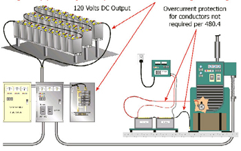
Figure 6. 480.3 Wiring and Equipment Supplied from Batteries
This rule has been changed by adding the wording “unless otherwise permitted by 480.4.”
Code Language:480.3 Wiring and Equipment Supplied from Batteries. Wiring and equipment supplied from storage batteries shall be subject to the requirements of this Code applying to wiring and equipment operating at the same voltage, unless otherwise permitted by 480.4.
Analysis of the Change:The rule that requires equipment and wiring supplied from storage batteries to comply with other requirements in the Code has been modified to cover a particular situation. A battery bank having an output of 120 volts is required to meet Code rules covering that same voltage and applies to elements of the system, such as wiring, overcurrent protection, and equipment. The new wording identifies a situation where this rule is not to apply and it involves the connection from storage batteries to a prime mover.
600.32 Neon Secondary Circuit Conductors, Over 1000 Volts, Nominal [See figure 7]
600.32(B) Insulation and Size
Type of Change:Revision
Summary of the Change:
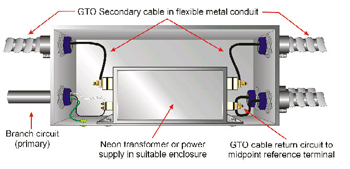
Figure 7. 600.32 Neon Secondary Circuit Conductors, Over 1000 Volts, Nominal
This section has been revised by changing the wording “”listed for the purpose, rated for the voltage”” to read “”listed as Gas Tube Sign and Ignition Cable Type GTO, rated for 5, 10, or 15 kV.””
Code Language:600.32(B) Insulation and Size. Conductors shall be insulated, listed as Gas Tube Sign and Ignition Cable Type GTO, rated for 5, 10, or 15 kV, not smaller than 18 AWG, and have a minimum temperature rating of 105°C (221°F).
Analysis of the Change:GTO cable has not been specifically recognized in the Code except as a reference in 600.32(E) even though it is a standard type of conductor used as secondary conductors for neon lighting. The revised wording should provide a better understanding of Type GTO cable and its use. GTO cable is intended for use with gas tube signs, oil burners, and inside lighting and is not a general-purpose wiring. Additional information on the cable can be found under Gas Tube Sign and Ignition Cable (ZJQX) in the UL General Information for Electrical Equipment Directory.
680.2 Definitions: Through-Wall Lighting Assembly [See figure 8]
Type of Change:New
Summary of the Change:
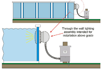
Figure 8. 680.2 Definitions: Through-Wall Lighting Assembly
A new definition of through-wall lighting assembly has been added in 680.2.
Code Language:680.2 Through-Wall Lighting Assembly. A lighting assembly intended for installation above grade, on or through the wall of a pool, consisting of two interconnected groups of components separated by the pool wall.
Analysis of the Change:This is a new type of underwater luminaire (lighting fixture) and it is not specifically defined within the article. This addition provides a general description of the product and is helpful in recognizing the equipment as permitted by the Code and distinguishing it from other luminaire assemblies.
760.2 Definition: Abandoned Fire Alarm Cable [See figure 9]
Type of Change:New
Summary of the Change:
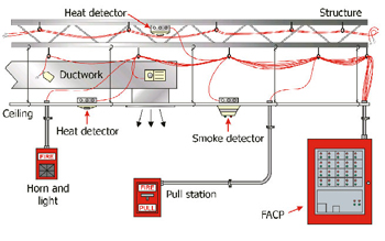
Figure 9. 760.2 Definition: Abandoned Fire Alarm Cable
A new definition of abandoned fire alarm cable has been added to 760.2.
Code Language:760.2 Abandoned Fire Alarm Cable. Installed fire alarm cable that is not terminated at equipment other than a connector and not identified for future use with a tag.
Analysis of the Change:This new definition provides information that will help determine what constitutes abandoned fire alarm cables in buildings. This change is associated with the one made in 760.3(A) for the removal of abandoned cables covered by this article. Two specific conditions are associated with determining whether or not a cable is considered as abandoned. One is that it does not terminate at equipment other than a connector and the other is that it is not identified by a tag for future use.
820.40 Cable and Primary Protector Grounding [See figure 10]
820.40(A) Grounding Conductor
820.40(A)(4) Length
820.40(A)(4) Exception
Type of Change: New
Summary of the Change:
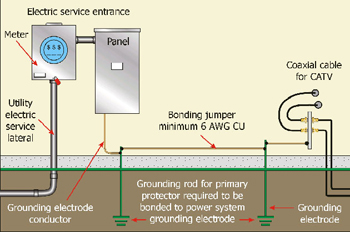
Figure 10. 820.40 Cable and Primary Protector Grounding
An exception new 820.40(A)(4) has been added to permit a ground rod for the primary protector with a bonding connection to the power system electrode.
Code Language:820.40(A)(4) Length. The grounding conductor shall be as short as practicable. In one- and two-family dwellings, the grounding conductor shall be as short as practicable, not to exceed 6.0 m (20 ft) in length.
Exception: In one- and two-family dwellings where it is not practicable to achieve an overall maximum grounding conductor length of 6.0 m (20 ft), a separate ground as specified in 250.52 shall be used, the grounding conductor shall be grounded to the separate ground in accordance with 250.70, and the separate ground bonded to the power grounding electrode system in accordance with 820.40(D).
Analysis of the Change: The points of connection of the electric service and community antenna television and radio distribution systems to a dwelling are not always in a common location. In those situations, keeping the length of the grounding conductor from the coaxial cable to the power system electrode to a maximum length of 6 meters is not practical. The exception included in new 820.40(A)(4) provides for a separate grounding electrode to be installed for the coaxial cable shield with a bonding connection to the power system electrode. This provides for a connection to earth for the coaxial cable shield with a short length of grounding conductor but also fulfills the requirement for connecting to the power system grounding electrode system. This provides a reasonable alternative to the more desirable situation where the antenna cable shielding cannot be grounded directly to the same electrode system used for the electric service.