With technology rapidly advancing, new developments in sensing and process control have increased the number of products using intrinsically safe or nonincendive circuits as their protection technique for hazardous (classified) locations as defined in Articles 500 through 505 of the 2002 National Electrical Code ANSI/NFPA 70 (NEC)1. With lower installation and maintenance costs, these protection techniques have found increased favor in applications traditionally requiring explosionproof devices. Though these concepts have been in use in industry for many years, some confusion still exists in regards to the installation of these devices. Following the proper installation requirements is important to the overall safety of intrinsically safe and nonincendive circuits.
Intrinsically Safe Circuits and Nonincendive Circuits
Intrinsically safe circuits and nonincendive circuits use the same basic concept to minimize the risk of ignition of hazardous atmospheres. Both rely on energy limitation with some important differences.
When determining the inability of a circuit to cause ignition of a flammable gas or vapor, it is necessary to consider not only the voltage and current available, but also the capacitance and inductance in the circuit. Since most circuits contain energy storage components such as capacitors and inductors, the energy stored by these components must be considered when determining the energy available in the circuit. The addition of capacitance or inductance to a circuit that is otherwise incapable of causing ignition may cause the circuit to become ignition capable. This is especially critical when considering fixed equipment interconnected by cables. These cables typically have known values of capacitance and inductance which must be considered in the final system installation. Before considering how the capacitance and inductance can be accounted for in a system, it is helpful to have a brief understanding of the equipment. The following definitions, taken from NEC 500.2 and 504.2, are provided for types of equipment related to fixed installations of intrinsically safe and nonincendive circuits.
Associated Apparatus.“Apparatus in which the circuits are not necessarily intrinsically safe themselves, but that affect the energy in the intrinsically safe circuits and are relied on to maintain intrinsic safety.” This type of equipment contains components that are designed to limit the voltage and current available to intrinsically safe equipment to which it is connected. Associated apparatus is generally intended to be installed in unclassified locations, though it can be installed in classified locations if another protection technique, such as an explosionproof enclosure, is used.
Intrinsically Safe Apparatus.“Apparatus in which all the circuits are intrinsically safe.”
Associated Nonincendive Field Wiring Apparatus.“Apparatus in which the circuits are not necessarily nonincendive themselves but that affect the energy in nonincendive field wiring circuits and are relied upon to maintain nonincendive energy levels.”
Nonincendive Field Wiring Apparatus.“Apparatus intended to be connected to nonincendive field wiring.”
Control Drawing.“A drawing or other document provided by the manufacturer of the intrinsically safe or associated apparatus, or of the nonincendive field wiring apparatus or associated nonincendive field wiring apparatus, that details the allowed interconnections between the intrinsically safe and associated apparatus or between the nonincendive field wiring apparatus or associated nonincendive field wiring apparatus.” Nonincendive field wiring systems and intrinsically safe systems shall be wired in accordance with the control drawing, as required by 501.4(B)(3), 502.4(B)(3), 504.10 and 505.15(C)(1)(g). The control drawing identification is required to be marked on the product.
Combination of Apparatus
Associated apparatus and intrinsically safe apparatus may be combined to form intrinsically safe systems. Much in the same way, associated nonincendive field wiring apparatus and nonincendive field wiring apparatus may also be combined to form a system. These combinations of apparatus are required to be listed together as a complete system or the associated apparatus and the field device are listed separately and then must satisfy additional requirements.
Intrinsically Safe and Nonincendive Systems
Apparatus listed as a system are easier to install since all aspects of the installation are defined on the control drawing provided with the equipment. Figure 1 is a simplified example of a system control drawing:
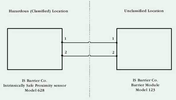
Figure 1. Figure 1 is a simplified example of a system control drawing
On the system control drawing, each piece of equipment that may be connected in the system is defined specifically by manufacturer and part number. Only the specific equipment included on the control drawing may be connected into the system. Other equipment, including portable communication devices, may not be used since any additional equipment could add either energy storage components or additional power sources which have not been evaluated in combination with the circuits. Additional equipment could therefore render the circuit ignition capable. Additional guidance for intrinsically safe systems can be found in Wiring Practices for Hazardous (Classified) Locations Instrumentation Part 1: Intrinsic Safety, ANSI/ISA RP12.62 as indicated in NEC 504.1.
It should be noted that the control drawing provides information regarding the interconnection cable. In some cases, the drawing will indicate a maximum length of cable to be used between the pieces of equipment. In other cases, a maximum allowable value of capacitance and inductance is given and it is necessary to calculate the allowable length of cable based on its specified capacitance and inductance per unit length. The capacitance and inductance of the cable shall either be taken from the cable manufacturer’s datasheet for the cable, or when not available, then standard values of 60 pF/ft for capacitance and 0.2 mH/ft for inductance are to be used. These values will be found on the control drawing, and are taken from the Standard for Safety, Intrinsically Safe Apparatus and Associated Apparatus for Use in Class I, II, and III, Division 1, Hazardous (Classified) Locations, ANSI/UL 9133.
Entity Concept
Associated Apparatus Entity Parameters
Associated apparatus which has been assigned entity parameters, whether providing intrinsically safe or nonincendive field wiring connections, are assigned the parameters shown below. Where two designators are shown, they are interchangeable.
Voc or Uo, this represents the maximum open circuit voltage that may be present at the specified terminals under the most adverse conditions.
Isc or Io, this represents the maximum short circuit current that may be present at the specified terminals under the most adverse conditions.
Ca or Co, this represents the maximum capacitance that may be connected to the specified terminals without invalidating safety.
La or Lo, this represents the maximum inductance that may be connected to the specified terminals without invalidating safety.
In some cases associated apparatus may also be provided with a Po and/or a Lo/Ro parameter. The Po parameter represents the maximum output power from the specified terminals. The Lo/Ro parameter is an inductance to resistance ratio and indicates the maximum inductance per ohm of resistance that may be safely connected to the specified terminals of the associated apparatus.
Intrinsically Safe and Nonincendive Field Wiring Apparatus Parameters
Intrinsically safe and nonincendive field wiring apparatus are provided with their own unique set of parameters. It should be noted that these parameters are based on maintaining a circuit that is not ignition capable and are not necessarily related to the proper functioning of the equipment. This equipment is assigned the parameters shown below.
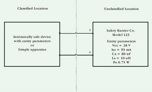
Figure 2. Figure 2 is a simplified control drawing for an associated apparatus
V max or Ui, this represents the maximum voltage that may be connected to the specified terminals of the device to maintain safety. Operational voltages are required to be lower than this parameter.
Imax or Ii, this represents the maximum current that may be connected to the specified terminals of the device to maintain safety. Again, the operational current will be lower than this parameter.
Ci, this represents the apparent capacitance at the specified terminals of the device.
Li, this represents the apparent inductance at the specified terminals of the device.
Pi, this represents the maximum power that may be supplied to the specified terminals to maintain safety. Operational limits will be lower than this power value.
Li/Ri, this represents the maximum internal inductance to resistance ratio at the specified terminals.
Combining Associated Apparatus and Field Devices
When combining associated apparatus with field devices, it is necessary to use the above noted entity parameters. The entity parameters of the associated apparatus must be compared with the entity parameters of all field devices connected into the system. When compared, the entity parameters must satisfy the conditions shown in Table 1.
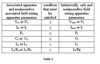
Table 1
To illustrate the use of these parameters, the following two drawings are provided. Figure 2 is a simplified control drawing for an associated apparatus. Figure 3 is a simplified control drawing for a field device.
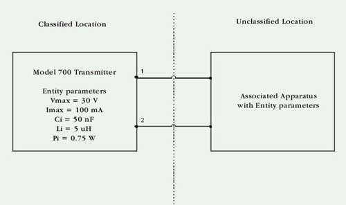
Figure 3. Figure 3 is a simplified control drawing for a field device.
On the control drawing for the associated apparatus, the Voc parameter is 28 V. Since this value is less than or equal to the Vmax of the field device, 30 V, the parameters satisfy the required relationship. The same holds true for the Isc and Imax values, since 93 mA is less than 100 mA. Next, a determination of the maximum allowable cable length is required. The total amount of capacitance at the terminals of the field device, Ci, plus the total capacitance in the cable, Ccable, cannot exceed the allowable capacitance of the associated apparatus, Ca. Therefore, the difference between the Ca of the associated apparatus and the Ci of the field device will provide the maximum value of capacitance allowed in the cable. In this case, the cable could have 30 nF of capacitance (80 nF minus 50 nF). Assuming the cable used in the system had a maximum capacitance of 60 pF/ft., a cable length of 500 ft. could not be exceeded. A similar calculation would need to be made for inductance, and the shortest cable length calculated between inductance and capacitance would be the maximum allowed.
When multiple field devices are connected to the same terminals of an associated apparatus, the Ci value of each field device must be added; the same applies to the Li values.
On the control drawings of certain types of associated apparatus with multiple circuits, an additional set of entity parameters can be found. These parameters are designated Vt and It, and are provided in place of or in addition to Voc and Isc. The parameter Vt is defined as the maximum open circuit voltage that can appear across any combination of terminals of a multiple circuit associated apparatus. Similarly, It is defined as the maximum current that can be extracted from any combination of terminals of an associated apparatus. In all situations, it is important that the associated apparatus be used only as described on the provided control drawing.
Other Notes on Control Drawings
In addition to details about the interconnection of the circuits in an intrinsically safe or nonincendive circuit combination, additional information is provided on control drawings. This information may include, but is not limited to, the following:
- The maximum nonhazardous location voltage, often designated Um, is the maximum voltage that can be applied to each of the non-intrinsically safe terminals of an associated apparatus without affecting intrinsic safety. Generally, this voltage is 250 V, though other values are possible. Since associated apparatus is evaluated to determine that it can maintain intrinsic safety even under fault conditions at its non-intrinsically safe terminals up to and including the Um value, the installer of the equipment must ensure that the equipment powering the associated apparatus does not use, store or generate in excess of this voltage.
- Grounding considerations (see below for additional details)
- Restrictions on routing, insulation or types of cables
- Restrictions on the types of associated apparatus to be used
Simple Apparatus
While the entity concept described above considers that both the associated apparatus and field device have been listed with the appropriate parameters, there are field devices that can be installed and considered intrinsically safe or nonincendive even though they do not carry entity parameters. Such a device is known as simple apparatus, which is defined in 504.2 as an electrical component or combination of components of simple construction with well defined electrical parameters that does not generate more than 1.5 V, 100 mA and 25 mW, or a passive component that does not dissipate more than 1.3 W and is compatible with the circuit in which it is used. Some examples of simple apparatus include passive components such as switches, junction boxes with terminal blocks, resistance temperature devices (RTDs) and LEDs, and sources of generated energy such as thermocouples and photocells. These types of devices are not required to be listed per 504.4, and can be installed using the entity parameters for the associated apparatus as described above for determining the allowable cable length for an acceptable connection.
Grounding
Correct grounding is critical to maintaining the safety of many systems. For example, a common type of associated apparatus is a shunt zener diode barrier, which uses zener diodes to clamp the voltage at its intrinsically safe circuit terminals to the value specified for its Voc or Uo entity parameter. In order for these diodes to perform this function, they must have a fixed reference to earth ground. These types of barriers are provided with ground terminal, and their control drawings provide information on the requirements for connection to this terminal. When the associated apparatus is connected to an intrinsically safe device, it is normally required that the intrinsically safe device be isolated from earth ground. This is to prevent the possibility of a ground loop occurring between the intrinsically safe device and the ground terminal of the associated apparatus. Since the voltage drop in the ground path between the devices is unknown, this could have an adverse affect on the intrinsic safety of the connection. This is not a concern with some other types of associated apparatus, e.g., galvanically isolated barriers, which generally use a transformer and are not required to be grounded to maintain intrinsically safe circuits. This type of associated apparatus is sometimes required for certain types of intrinsically safe equipment, e.g., devices such as pressure transducers that cannot be isolated from earth ground due to their construction. The requirements for grounding of an intrinsically safe circuit are provided in 504.50. Always refer to the control drawing for the specific devices to ensure that the correct grounding and grounding electrode connections are made.
Wiring
Due to the limited energy levels available in intrinsically safe and nonincendive field wiring circuits, wiring methods normally not permitted in hazardous (classified) locations can be used in their installation. For example, in a Division 1 classified location, installation normally requires threaded rigid metal conduit. However, per 504.20, intrinsically safe circuits may be installed using any wiring method allowed by the NECâ for unclassified locations. Similarly, per 501.4(B)(3), 502.4(B)(3) and 505.15(C)(1)(g), nonincendive field wiring circuits can also be installed using unclassified location wiring methods. It is important to note, however, that these circuits may require wires or cables having additional insulation to guarantee suitable separation. NEC 501.4(B)(3), 502.4(B)(3), 504.20 and 505.15(C)(1)(g) requires that different circuits be installed in separate cables or in cables where each conductor is within a grounded metal shield or each conductor has a minimum insulation thickness of 0.25 mm (0.01 in.).
Separation of Intrinsically Safe and Non-Intrinsically Safe Wiring
To reduce the possibility of their interconnection, additional requirements exist for the separation of intrinsically safe and non-intrinsically safe circuits. NEC 504.30(A) requires a minimum separation distance of 50 mm (2 in.) be provided between intrinsically safe and non-intrinsically safe conductors. This separation may also be accomplished by using a grounded metal or insulating partition, or by locating either of the circuits in a grounded metal shield capable of carrying the maximum prospective fault current should either circuit be connected to earth.
Identification of Intrinsically Safe Field Wiring
Raceways, cable trays, and other wiring methods for intrinsically safe system wiring shall be identified with permanently affixed labels with the wording “Intrinsically Safe Wiring” or the equivalent. NEC 504.80 states that the distance between labels shall not be more than 7.5 m (25 ft.). Alternatively, color coding may be used as a method of identification provided that the color light blue is used, and that no other conductors or wiring are colored light blue.
Summary
The incorrect installation of intrinsically safe and nonincendive circuits can result in a system that could become ignition capable. Therefore, care must be exercised when determining the suitability of the combinations of associated apparatus and field devices. Furthermore, it is necessary to follow the applicable requirements in the Code concerning grounding, wiring, separation and identification. The control drawing provided with each piece of equipment provides the necessary information to determine the acceptability of the installation.
1National Electrical Code(NEC), ANSI/NFPA 70, National Fire Protection Association, Inc. (NFPA), Quincy, MA USA, 2002.
2 ANSI/ISA RP 12.6-1995, Wiring Practices for Hazardous (Classified) Locations Instrumentation Part 1: Intrinsic Safety, ISA – The Instrumentation, Systems, and Automation Society, Research Triangle Park, NC USA
3 ANSI/UL 913, Intrinsically Safe Apparatus and Associated Apparatus for Use in Class I, II, and III, Division 1, Hazardous (Classified) Locations, Underwriters Laboratories Inc., Northbrook, IL USA.