Have you run into a new electrical product on the job site lately? Have you seen something new and wondered where it came from? Have you noted that it was listed but didn’t know how it was intended to be installed or used? Have you had to call for help or delay an inspection until you got more information? Obviously, those situations are tough on your image as the “all-wise, all-knowing” electrical inspector. But new products are a reality in the marketplace and we need to be able to deal effectively with them when they arrive.
Fortunately, with a little effort, we can do just that. Time is on our side. New products don’t just pop up overnight. The effort to bring a new product to the market is a long and involved process. During this process, there are many opportunities for inspectors and others to observe the progress and even to provide input into the development of a new product.
This article is intended to shed some light on the typical processes involved in the development of new products and to point out those areas where you can be informed and involved. To explore these processes, we will track the progress of a product currently in development by an electrical cable manufacturer. A real product was used to better show the process from concept to listing and to address the issues of why new products are developed and how the testing system works in real life. This particular product was selected because it highlights the testing and review processes involved in the development of a new product and to give inspectors an advance look at a new product that will be showing up on job sites in the near future.
Both the manufacturer, Alflex Corporation, and the testing lab, Underwriters Laboratories, Inc., assisted IAEI in preparing this informational article. The product, MC Smart, is a new type of metal-clad cable with an interlocking metal armor that is acceptable for use as an equipment grounding conductor.
The Concept
Metal-clad cable is available in three types: interlocking metal-tape armor, smooth tube, and corrugated tube. This article focuses on the evolution of the most common type of MC cable used for today’s applications, which is the interlocking metal armor. In 1999, a manufacturer recognized the expanding demand for MC cable of the interlocking metal tape-type in a variety of uses. This demand was fueled by the many advantages MC cable offered the electrical industry. While cable wiring methods offer the industry a viable and practical choice in many applications, one must also be familiar with the limits of each specific wiring method for a given installation, application or condition. This information is found in the NEC article covering each wiring method under the “Uses Permitted” and “Uses Not Permitted” sections. In applications where they are acceptable, the industry continues to show a preference for cable wiring methods. Cable wiring methods are flexible, so they are easier to handle and install. Cable wiring methods come with the conductors installed, so there is no need to pull wire on the job site. And, most importantly, cable wiring methods are generally more economical than other acceptable wiring methods. Two commonly used types of cable are MC and AC cable, both with interlocking metal tape armor. While similar, there are significant differences between MC and AC cable. MC cable can include any number of conductors. AC cable is restricted to a maximum of four conductors in a cable. MC cable can include conductors in sizes up to 2000 kcmil. AC cable is limited to conductors in sizes no larger than 1 AWG. MC cable can include optical fibre elements. AC cable is not permitted to do so. MC cable also has a wider range of permitted uses such as damp and wet locations and places of assembly. However, the metal armor of AC cable is listed as an equipment grounding conductor where MC cable is not, and listed AC cables that include a green insulated grounding conductor meet the redundant grounding requirements for branch circuits in patient care areas of health care facilities.

Figure 1. MC Smart required a change in the UL 1569 Standard for Metal-Clad Cable – approximately 4 years in development
Of course, one of the most frequent requests from the industry was for an MC cable that could be used in health care facilities. Although corrugated and smooth tube MC cables can be constructed for use in health care facilities, their acceptability in the industry continues to be limited by a relatively higher cost and the added difficulties in handling and installation. On the other hand, MC cable of the interlocking armor type could not be recognized for use in health care facilities unless the construction was somehow modified so that the metal sheath could be listed as an equipment grounding conductor. The manufacturer also recognized the significant changes to Article 250 in the 1999 NEC. New performance requirements in Article 250 clearly identified the need for the equipment grounding conductor to provide an effective fault-current path throughout the premises wiring system. The manufacturer noted that any new construction of MC cable would require a much lower impedance armor to meet the stringent requirements of Article 250. However, it was obvious that both safety and the range of permitted uses could be greatly increased with an MC cable with interlocked armor listed as an equipment grounding conductor; so, the manufacturer decided that the possibility of constructing an MC cable of that type would be worth pursuing.
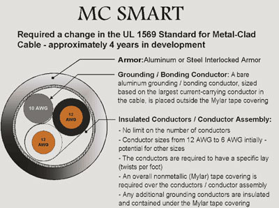
Figure 2. MC Smart required a change in the UL 1569 Standard for Metal-Clad Cable – approximately 4 years in development
The Business Issues
As with any business venture, the manufacturer had to work within some business constraints.
—Cost of development was number one. There is a limit to how much can be spent on product development. That typically is the amount that can hopefully be recovered over some reasonable period of time after the product is on the market. Money spent on research and development of new products is always a gamble. A lot of money is spent developing products that never make it to the market.
—Cost of necessary retooling was another. A new cable that required all new equipment to manufacture would greatly increase the overall investment and most likely be impractical. Ideally, the new product should be one that could be constructed with existing equipment.
—Cost of manufacture was the third. Assuming a new cable could be constructed using existing equipment, the overall costs of producing it had to be such that it would be competitive with other cables already on the market.
The Construction Solution
Several possible changes in cable construction were considered and reviewed. Ultimately, it was determined that a bare aluminum grounding/bonding conductor should be added to the cable assembly. This conductor would be located outside of the Mylar wrap around the conductors and be in continuous, intimate contact with the armor for the entire length of the cable. The goal was to create an assembly, consisting of the metal armor and the bare aluminum grounding/bonding conductor, that would provide an effective path for fault current and qualify the armor as an equipment grounding conductor. This concept is somewhat similar to the construction of AC cable but the differences are significant.
AC cable has a bare aluminum strip, equivalent to 16 AWG, which runs straight inside the metal armor. There are two limitations with this type of construction. One is that the conductors in the cable spiral (twist) while the bare aluminum strip runs straight. Where there is a void under the strip, it may not be held in tight contact with the armor. The second is that the current-carrying capacity of a 16 AWG aluminum strip is limited, which in turn limits the amount of fault current that the cable armor can safely conduct.
The proposed construction of the new MC cable is quite different from that of AC cable.

Figure 3. AC Cable – constructed in accordance with UL 4 Standard for Armored Cable – in use since the early 1900s
First, the bare aluminum grounding/bonding conductor used in the cable is much larger than 16 AWG. The size of the bare aluminum grounding/bonding conductor is based on NEC Table 250.122. Cables with 12 AWG copper current-carrying conductors are constructed with a 10 AWG bare aluminum grounding/bonding conductor. Cables with larger current-carrying conductors have appropriately larger sized bare aluminum grounding/bonding conductors. This provides the capacity to safely conduct the maximum fault current that can be imposed on it based on the size of the current-carrying conductors in the cable.
Second, the bare aluminum grounding/bonding conductor follows the spiral of the conductors in the cable rather than being laid straight. The spiraled conductors form a more perfect circle allowing the metal tape to be wound very snugly around the conductors and assuring that the bare aluminum grounding/bonding conductor is in continuous contact with the armor at every point in the cable.

Figure 4. MC Smart cable
Third, the cable armor is constructed with aluminum armor rather than steel. The lower resistance of the aluminum armor combined with the larger bare aluminum grounding/bonding conductor results in a very low resistance per foot of cable.

Photo 1. AC/MC cable – different physical characteristics
The manufacturer determined that:
— The new construction would enable the armor to serve as an equipment grounding conductor.
— It could be manufactured on their existing equipment.
— The cost of manufacture would be no more than that of standard MC cable.
Given these findings, the manufacturer felt comfortable in moving forward and submitting the product for evaluation, testing and listing.
The Evaluation, Listing and Testing Process
Any product manufacturer or individual can submit a product for listing. All it takes is time and

Photo 2. AC/MC cable comparison in ground path
money. The submitter tells the listing agency what function the product is intended to perform. The listing agency determines what testing is required both to verify the submitter’s claims and to assure that the product is safe to use. If the product is of a type where standard tests have already been developed and a standard exists, then the product is tested to that standard. If the product is different than existing products and not adequately covered by the existing product standards, then the testing agency must develop new tests to verify its safety and performance.
One of the reasons for using the new MC cable in this example is that it falls into both categories. A standard exists for MC cable and the new product would be subjected to all of the tests normally required for an MC cable. However, the manufacturer also indicated that the interlocked armor assembly would serve effectively as an equipment grounding conductor. The existing safety standard does not include tests and requirements for this function so the testing lab would have to develop a test program to evaluate and verify this additional claim.
The manufacturer of this new MC cable elected to submit their product to Underwriters Laboratories, Inc. UL is not only the largest testing organization in the United States, it also develops the safety standards for the majority of electrical material and equipment. It is interesting to note that UL spent nearly a year reviewing the request and the product to

Photo 3. Smart MC provides grounding path to receptacle outlet
determine if they would accept it for testing. They reviewed data and samples of the cable and performed many of the tests already conducted by the manufacturer. They also determined what testing would be required to verify the claim that the armor would provide an effective equipment grounding conductor. This pre-testing was to assure that the new cable would meet the minimum standards for MC cable and that it was reasonable to proceed with the formal testing process. UL elected to accept the new cable for testing and began the official review.
The testing standard for Type MC cable is UL Standard for Safety 1569. UL performed all of the tests required by this standard. UL 1569 tests for strength and flexibility include:
Crush: required to withstand average of 1000 lb/ft pressure in ten tests.
Impact: 10 lb weight dropped from 18 height ten times; must pass at least 8 out of 10 tests.
Tension: 150 lb load on armor for 5 minutes without deformity.
Flexibility: wound around a 5 ½ mandrel without damage to the armor.
Cold bend: wound around a 5 ½ mandrel in low temperature without damage to the armor.
Tightness of armor: must hold 30 lbs for 60 sec with no more than ½ conductor movement.
The new MC cable successfully passed these tests.
UL 1569 also includes basic dielectric tests for insulation and resistance:
Voltage withstand: conductors must carry 3000 volts without faulting to the armor.
DC resistance: resistance through the armor and bare aluminum grounding/bonding conductor.
The DC resistance tests were performed both before and after the standard tests for physical strength listed above. The new MC cable successfully passed these tests. In point of fact, the new MC cable in sizes 12/2, 12/3, and 12/4 averaged 1.5 ohms per 1,000 feet. In comparison: 1,000 feet of the aluminum armor of standard MC cable, not including the green insulated grounding conductor, has a resistance of 20.6 ohms; 1,000 feet of AC cable with aluminum armor has a resistance of 4.6 ohms, and 1,000 feet of 12 AWG CU conductor has a resistance of 1.73 ohms. This significant test result shows that the new MC cable has a lower resistance than any currently produced armored cable, either AC or MC, and is even lower than the equivalent copper equipment grounding conductor required by code.
UL selected specific tests from UL 514B, Standards for Fittings, to evaluate the cable connected to boxes with listed fittings. These tests included:
Fitting torque: fittings torqued to recommended values with no damage to cable or fitting.
Bend: cable bent 90o and 180o with no damage to cable or loosening of fitting.
Pull: cable and fitting supported 75 lbs. for five minutes without damage.
Repeated resistance: tested consistency of resistance with 30 amps DC current. These tests were conducted on each sample both before and after the required performance tests.
The new MC cable successfully passed these tests.
UL determined that fault-current tests from UL 1 and 514B would be appropriate for measuring the capacity of the fault-current path created by the combined bare aluminum grounding/bonding conductor and interlocked armor of the cable assembly. These tests include fittings to be consistent with the normal installation of the cable.
UL 1 Fault Current Test:–6´ of cable with fittings on both ends must carry 470 amps for 4 seconds.
UL 514B Current Test: cable and fitting connection must carry 1180 amps for 4 seconds.
In both tests, the cable must not melt or otherwise deform in such a manner that the fault-current path is interrupted. Continuity tests are conducted after each of the current tests.
All of the repeated resistance and current tests were conducted with samples of the currently listed fittings for MC cable. These included the squeeze, duplex/twin, saddle, 90-degree, 2-screw strap, single screw strap and E-Z lock. The new MC cable successfully passed these tests.
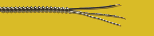
Photo 4. Smart MC without terminal fitting
This rigorous evaluation and testing proved that the new MC cable would serve effectively as an equipment grounding conductor. Based on these favorable test results, UL moved on to the next step in the testing and listing process.
The Review Process
Up to this point, nearly four years into the process, most of us would probably not have heard a word about this new product. The manufacturer is not going to advertise a product that is still in the testing and evaluation process and normally does not go public until listing is obtained.
However, in the review process, there are information sources available to us. UL has an Electrical Council that consists of nearly 60 electrical inspectors from jurisdictions around the country. This council assures that UL is made aware of field problems encountered with their listed products. The council is also provided with information on UL activity and has access to their ongoing testing activity. The names of these council members are available on a UL web site. Go towww.ul.com/councilsand click on 2003 Electrical Council Report. The members are listed as well as a report on the issues discussed at the meeting. Find a member you know or who works close to you and you have an information source into the workings of UL. Nearly all Electrical Council members are IAEI members and typically report on UL activities to their sections, chapters and divisions.
Most testing agencies have some process for communicating with the electrical industry.
In addition, UL has standards technical panels (STPs) for most of their safety standards that review any proposed changes to the standard. These panels consist of volunteers from the electrical industry that have an interest in the products covered by that standard. Whenever a change to a standard is proposed, the standards technical panel is notified of the proposed change and the rationale for it and are allowed to vote on whether UL should proceed. A two-thirds vote in favor is required for approval. This activity is part of a formal ANSI Standard process and subject to ANSI review. The membership of standards technical panels is not available on the UL web page but general information is available atwww.ulstandardsinfonet.ul.com/stp/.
The standards technical panel for UL 1569 is STP 4. There are 23 members. Seven of these members fall into the category of user, which includes inspectors and others involved with products in the field, four are general members, two are non-voting UL representatives and ten are producers, representatives of companies that manufacture wire or cable. Some of the companies represented on STP 4 include Southwire, Pirelli Cable, Alcan Cable, AFC Cable and, of course, Alflex. Specific membership information may be available from the panel secretary.
In our example case, the standard for MC cable (UL 1569) required a change to permit the new cable construction. The present standard requires a nonmetallic or Mylar wrap around all conductors in the cable to separate them from the metal sheath. This wrap provides strength to the conductors and additional protection against a fault to the armor. Obviously this conflicts with the need for the bare aluminum grounding/bonding conductor to be in contact with the armor. Based on the satisfactory test results of the new cable, UL proposed a change to the MC cable standard to permit the bare aluminum grounding/bonding conductor to be located outside of the Mylar wrap. In the change to the standard, the new type construction was proposed as an acceptable alternate method of construction for MC cable. The standard would then permit MC cable to be manufactured both as it is currently constructed and in the new construction. This proposed change to UL 1569 was submitted to Standards Technical Panel 4 for their review. It should be noted that the change to the product standard, although driven primarily by one manufacturer, provides an opportunity for other manufacturers of MC cable to produce cable assemblies that meet this criteria.
As noted, members of the standards technical panel are volunteers, accepted by UL based on their experience and their interest in the products covered by the standard. Several electrical inspectors are on the panel, all of whom are IAEI members. The importance of their role in this process cannot be overstated. Inspectors generally have a good knowledge of field practices and the problems that can occur during installation. More importantly, they are the most objective reviewers since they have no financial interest in the product. Inspectors on STP 4 raised several meaningful issues regarding potential problems with the new cable. Some felt that the testing reports were incomplete or unclear as to what was actually tested. They felt they needed some clarification on that issue. Several were concerned that the new cable would be confused with standard MC cable or even with AC cable, which could result in misuse. Some were also concerned that the method of terminating the bare aluminum grounding/bonding conductor would be confusing to installers. There was some definite interest in assuring that installation instructions would be required as a part of the listing.
The manufacturer noted each of these issues and has taken steps to address them.
On the testing issues, UL was requested to clarify the testing procedure so that no questions remained regarding what was tested and what the results were. Most important was clarification that the new cable had been tested both with the bare aluminum grounding/bonding conductor simply cut off and also with it folded back over the armor and that these tests had been conducted with many different types of listed fittings.
On the “confusion with other cables” issue, the manufacturer has added marking on the neutral conductor in their cable with the wording, “Armor is Ground Path Component.” This wording not only provides useful information but, because it will appear only on the new type MC cable, serves as a unique identifier for the cable. Although this marking is only required on the marker tape in the cable, the manufacturer will voluntarily include the marking on the neutral conductor to aid in field identification of the cable both before and after installation.
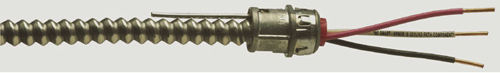
Photo 5. Groundpath terminated at fitting
In point of fact, this new type of interlocked armor cable construction will be the only type of interlocked armored cable to have a bare aluminum grounding/bonding conductor located outside of the nonmetallic (Mylar) overall conductor covering. This unique con-struction assures that the new type MC cable (MC Smart) cannot be confused with a standard interlocked armor MC or AC cable. In responding to the potential confusion issue, it became apparent that MC Smart could be readily identified at all stages of use.
Identifying MC Smart before it is installed: Look for the product tag and required installation instructions on the cable coil or reel, or look at the end of the cable for the bare aluminum grounding/bonding conductor outside of the Mylar wrap.
Identifying MC Smart after the armor end has been stripped: Look for the bare aluminum grounding/bonding conductor outside of the Mylar wrap or look for the printing on the white or gray conductor usually used as the neutral.
Identifying MC Smart after it is installed: Look for the printing on the white or gray conductor usually used as the neutral.
On the termination of the bare aluminum grounding/bonding conductor, the manufacturer will provide installation instructions to show how the conductor is to be treated. UL tests demonstrated that the bare aluminum grounding/bonding conductor could be cut off at the end of the cable—not terminated at all—and the assembly would perform effectively as an equipment grounding conductor. However, this manufacturer understands the potential for confusion regarding this product and has provided installation instructions that identify two acceptable termination methods.
The first method is to fold the bare aluminum grounding/bonding conductor back over the metal sheath before installing the fitting. This installation method has been tested with many types of listed fittings available for MC cable and found to be acceptable. This termination method was developed solely as another means to identify the new MC cable after installation.
The second method is to terminate the bare aluminum grounding/bonding conductor as if it were the equipment grounding conductor. This would require splice or termination devices listed for use with solid aluminum conductors at each termination. Although acceptable, this termination method is costly, time-consuming, and basically unnecessary. The metal armor of the cable and the bare aluminum grounding/bonding conductor together form an assembly which is designed and intended to be the equipment grounding conductor. The bare aluminum grounding/bonding conductor does not have to be terminated like a current-carrying conductor or an insulated equipment grounding conductor.
Editor’s Note: As this article was going to press, we were notified that the STP approved the standards change with the termination methods identified above. However, there was a concern that the fold-back method of termination might cause a problem with the proper installation of some fittings. In response, the manufacturer proposed a standards change to permit the grounding/bonding conductor to be cut off at the end of the armor. This is consistent with the testing of the cable, as noted above, and will provide a much better termination than the two presently approved. We will try to provide an update on this proposal when it is available. The manufacturer notes that the new cable will not be marketed until the termination issues are resolved.
On the “”installation instructions”” issue, the manufacturer has prepared a tag for the product that provides step-by-step installation instructions. Each step is clearly described and is also shown in a picture to assist the user. The manufacturer has requested and UL has agreed that installation instructions will be required by the standard. While the installation instructions for a TV or VCR may come in a 20-page manual, installation instructions for wiring methods are usually pretty minimal. The credit for these clear and helpful installation instructions goes to the inspectors on STP 4 who know better than most how important such instructions can be.
It’s important to note that these improvements in this product were all developed through the review process, prior to listing of the cable. The review process worked well to help us avoid confusion and potential misuse of the product and we didn’t have to red tag a single job to accomplish this.
Education and Advertising
How are they helpful to us? Advertising is a key element in product recognition leading, hopefully, to meeting industry needs and demands. This manufacturer, like others, advertises their current products and will be advertising the new cable in the near future. Advertisements include product information but are probably not the best way to get technical information on a new product.
Educational programs on new products are a unique form of advertising that can benefit both the manufacturer and the user. The review process has made the manufacturer well aware of the issues that need to be addressed when their new cable comes to the market. They have already taken several steps to educate the industry regarding their new cable.
— They have developed a one-page information sheet which describes on one side how the cable is constructed and how it is to be used. On the flip side, it describes the correct installation method and uses pictures to show each step.
— They have provided these same installation instructions, with text and pictures, on a tag to be included with each coil or reel of cable.
— They have worked with UL to have the installation instructions included in the standard so that anyone who manufactures the new cable will provide clear and helpful installation instructions.
— They have developed educational programs for presentations to inspectors, engineers, contractors, electricians and other interested parties.
— They have previewed their new cable at IAEI meetings and at the recent IAEI Jubilee in Orlando.
Will their educational efforts help us? Of course. We have the opportunity to be ahead of the information curve. We can be fully informed about the new product and how it is to be installed before it gets to the market.
This article demonstrates that a system exists to assure that new products are tested for safety and that we have an opportunity to be informed and even participate in the process.
The facts are:
— Manufacturers invest time and money to develop better and safer products.
— New products undergo comprehensive and objective testing for safety.
— There is a thorough, objective review process and inspectors have a meaningful voice in it.
— The listing process provides factual information on safe and proper use of products.
— Programs are generally available to educate the industry on changes and improvements.
— Both those in the industry and all end users benefit from new and safer electrical products.
And, of course, we can maintain our “all-wise, all-knowing” image on the job site.
Reference
The primary purpose of this article was to provide information relative to new product development, evaluation, testing, and listing. It is not intended in any way to promote one manufacturer more than another. Product safety standards are developed or modified based on need and demand and new inventions. Often a manufacturer will venture into development of a new product that causes a change to a safety standard that in effect allows their particular product to be safely introduced into the market and allows others to have the same opportunities to