All of us have ideas. Have you ever wondered how a new product idea is first conceived—is nurtured in somebody’s mind—and is refined into a finished new product for use?
The vast majority of new products ideas die a sudden death in the minds of the originators. A very few survive for a while and are developed to a certain stage before fading away for one or more reasons.
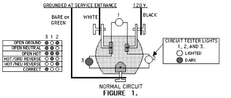
Figure 1. Figure 1 shows a normal three-wire circuit with polarity correct and an equipment grounding conductor. Lights 1 and 2 are lit. Light 3 is off, because there is no voltage at the white and green terminals.
Very, very few new product ideas are actually developed into the prototype stage for evaluation. Many of them die at this stage. Some of the reasons for this early demise of a new product prototype are:
- Insufficient push by the idea originator
- Lack of an adequate mentor for the new product
- Failure of the prototype to perform as expected
- Unacceptable ratio of cost to anticipated selling price
- Lack of needed financing
- Insufficient anticipated sales volume
- Unacceptability of the new product for listing or third party acceptance
- Inability to obtain product liability insurance
To illustrate the trails and tribulations a new product idea experiences, let’s look at one of my recent ideas.
A couple of years ago, I participated as an expert witness in litigation involving the electrocution of a plumber. An older home with an old two-wire wiring system was experiencing major renovations. An electrician installed a three-wire, 15-A, 125-V receptacle type GFCI on a two-wire circuit in the garage, as permitted by Section 406.3(D) of NEC-2005. But then, he installed an illegal jumper wire from the white terminal, normally the grounded circuit conductor, to the green, hex-headed terminal, normally the equipment grounded conductor. In a later disposition, the electrician is reported to have stated that he did this “to fool the electrical inspector.”
Unfortunately, somewhere in the house the black wire and the white wires had been transposed. In normal two-wire installations, this transposition would have not been a problem. Both black and white wires are fully insulated with 600-volt insulation. Until the recent requirement for polarization of 2-wire cord sets and power supply cords, it was a 50-50 situation as to which conductor and which lamp socket terminal was at 120 V.
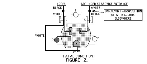
Figure 2. The fatal condition. Lights 1 and 2 are lighted, the same as the normal safe condition. The white terminal is energized at 120 V by the reversed polarity. The green terminal is at 120 V by the jumper from the white terminal.
In this case, however, the white wire was now energized at 120 V and thus the jumper wire energized all of the following at 120 V: the grounding terminals, the device mounting yoke, the wallplate screws, and all metal in contact. The black wire and terminal became the grounded circuit conductor and were connected to ground at the service.
The electrician tested the installation with a listed outlet circuit tester of the three-lamp type, and it indicated a correct installation. A plumber plugged a three-wire trouble light with metal lamp guard into the GFCI receptacle, crawled under the house to do plumbing, and was electrocuted by contact with the metal lamp guard.
It should be noted that the GFCI was doing its job. The GFCI function was being bypassed by the jumper.
As I investigated the accident, I was initially surprised that the outlet circuit tester showed that all was okay. As we look at the conditions and the construction of all of these three-wire circuit testers, we see that all listed, three-lamp outlet circuit testers would have shown that all was okay.
All of these testers have an indicating light between the hot and the grounded circuit conductor blades, that we will call light 1, a light between hot and the equipment grounding blades, that we will call light 2, and a light between the grounded circuit conductor and the equipment grounding blades, that we will call light 3 (see figures 1 and 2).
It doesn’t take a combination of a two-wire circuit, reversed polarity, and a jumper, intentional or unintentional, to cause serious unsafe signals from these testers. Let’s assume that a house has only two-wire circuits, correctly wired, black-to-black, and white-to-white. Section 406.3(D)(3) of NEC-2005 permits all the two-wire receptacles in the house to be replaced by three-wire receptacles, when protected by GFCIs and properly marked.
There are lots of scenarios, and I’m sure our inspectors can give us some others. At the Eastern Section meeting this year, I learned of a beaut. It seems that a small New England town with many nice decades-old Victorian homes built before equipment grounding conductors were required has most of its homes with two-wire branch circuits having reversed polarity. The white wire is energized at 120 V and the black wire is the grounded circuit conductor! It turns out that the authority having jurisdiction (AHJ) way back then believed that the color white was more appropriate as the hot conductor and black was better as the grounded circuit conductor!
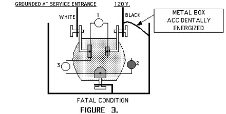
Figure 3. Figure 3 shows an example where the equipment grounding terminal has become energized.
The glaring need to straighten out the outlet circuit tester mess turned on my “Idea” light. With my limited electronics talent, I tried my best to build into the testers electronic components that would insure correct operation of these devices.
I realized that I needed a real pro, and I called on the best there is—my friend and co-worker from years ago at GE, Keith Howell.
Keith and I have a US patent pending with 26 claims that adds electronic circuitry and indication to circuit testers. We have modified UL-listed outlet circuit testers with all of the components fitting into the existing devices. These circuit testers have been extensively tested by two manufacturers, who agree that the samples solve the problems.
We are now in the process of attempting to have the products made and sold. We have contacted the manufacturers who have UL-listed outlet circuit testers and other manufacturers who might be interested.
With the tremendous work ahead of the electrical industry in rebuilding the electrical systems in New Orleans and the Gulf Coast area, we believe that such a product could make a significant contribution.
We are now at the most difficult stage of all—getting manufacturers to agree to make and sell new outlet circuit testers incorporating our patent pending circuitry.
The case can be made that proper warning on the packaging of the present circuit testers or on the circuit testers themselves should satisfy the concerns. We all know what happens to the packages. There’s not much room on the testers for more words.
With the existence of this new technology, the product liability playing field has changed considerably.
I have many existing devices in front of me right now as I write this. Four are still in their packages.
One blister-pack card states: “Lights indicate if wiring is correct.” Maybe this could be changed to: “Lights indicate either that wiring is correct, or that there is a fatal shock present.”
There are some cautions on the packaging. One states in three languages: “Warns against faulty wiring in 3-wire receptacles.” With the expanded usage of three-wire receptacles as replacements on two-wire branch circuits, as permitted by Section 406.3(D), there is a greater likelihood of problems.
We’ll keep plugging away to have outlet circuit testers corrected, either with our circuitry, or with other circuitry that accomplishes the equivalent safety goals.