In the July/August issue, we provided a glimpse of some of the more significant changes proposed and accepted for NEC-2008. This article is a continuation of that review. Once again, it is important to stress that this is a look at what was proposed and acted on by the code-making panels through the proposals stages of the NEC-2008 development process. These changes could be affected by public comments to the initial committee actions on these proposed revisions. The established deadline for public comments to the proposed changes is October 20, 2006 (5:00 p.m. est).
More Code-Wide Revisions
Photo 1. Disconnecting means capable of being locked in the open position. The provision for locking or adding a lock to the disconnect remains with the switch whether the lock is installed or not.
This first series of changes has to do with Code rules that include the words “capable of being locked in the open position.” Approximately thirty locations throughout the NEC use this wording in the requirements. The concept in all of these instances is the same and is related to safety for workers. Generally, where the Code requires a disconnecting means, it is required to be in sight from, or within sight from the equipment it controls. The term In sight from (within sight from, Within Sight) is defined in Article 100. In many of these disconnect location rules, there is also an allowance (usually by exception) that indicates the disconnecting means could be located out of sight from the equipment if the disconnect is capable of being locked in the open position. However, the wording differs from section to section. New concepts were introduced by CMP-11 in NEC-2005 that clarified the objective (intent) of that requirement. This resulted in a provision for locking or adding a lock to the disconnecting means to be installed on or at the switch or circuit breaker used as the disconnect and for the provision to remain in place with or without the lock installed (see photo 1). This is an important safety requirement for workers. It is logical that, for more consistent and uniform application of this rule, the language should be the same in the various rules that include this provision.
Revision: 240.86(A) Selected Under Engineering Supervision in Existing Installations
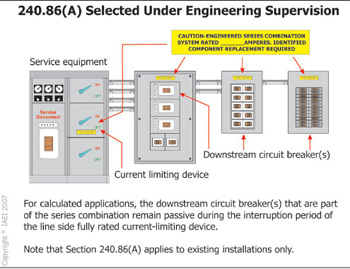
Figure 1. Engineered series rated overcurrent device combinations
The concepts in Section 240.86(A) were introduced in NEC-2005 and recognized a method of applying an engineered series rated combination of overcurrent protection that is selected under engineering supervision for existing installations only. This section has been revised this cycle to require specific field marking on equipment applied in engineered series rated combinations. An additional sentence has been added to clarify the operating characteristics of devices applied in combinations selected and applied under the provisions of this section. The new sentence reads as follows: “For calculated applications, the engineer shall ensure that the downstream circuit breaker(s) that are part of the series combination remain passive during the interruption period of the line side fully rated, current-limiting device.” Although application of this provision is not common, the revisions to this section provide needed details clarity for professionals choosing to apply it in existing installations (see figure 1).
Revision: 250.32(B)(1) Exception
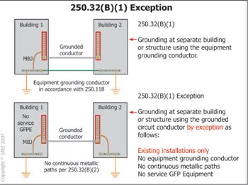
Figure 2. Grounding at separate buildings or structures
Section 250.32(B)(2) has been incorporated as an exception to Section 250.32(B)(1) and will apply to existing installations only. The revisions to this section are consistent with the efforts of Code-Making Panel 5 to continue to migrate away from the use of the grounded conductor for grounding on the load side of the service disconnecting means. The original proposal was to delete Section 250.32(B)(2) completely which would not have left any language that could be applied to existing installations. The changes in this section also restrict the application to existing installations only. The conditions specified in Section 250.32(B)(2) for use of the grounded conductor for grounding equipment were already restrictive in nature for new designs and installations contemplating its use. The effect of this revision is users having to develop designs and installations of feeders or branch circuits that include an equipment grounding conductor in accordance with the requirements of 215.6 and 250.32(B)(1) for all feeders or branch circuits installed to supply separate buildings or structures. This change should help reduce the number of designs that purposely invite the possibilities of inappropriate neutral-to-ground connections that can, and often do, happen later, which is uncontrollable by any NEC rule. Existing installations meeting the requirements of Section 250.32(B)(2) in previous editions of the NEC would be allowed to remain operational. However, the restrictive conditions of the new exception [former 250.32(B)(2)] still have to be met and are subject to approval of the applicable authority having jurisdiction (see figure 2).
Revision: 250.94 Bonding for Other Systems
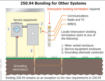
Figure 3. Intersystem bonding termination
This section has been completely revised by additional specific requirements for intersystem bonding and grounding terminations. The existing text has been retained and rewritten into an exception to the new requirements. This revision is one of several correlated changes (100 Definitions, 250.94, Chapter 8 Articles) to improve the requirements related to intersystem bonding and grounding of communication systems. The effect of this change inserts a requirement for a dedicated and well-defined location for terminating the bonding and grounding conductors on a specific set of terminals or a bonding bar provided for that purpose. The proposed termination would have sufficient capacity to handle multiple communication systems (telecom, satellite, CATV) on premises, but not less than three terminals are required. Specified locations for these termination points for the intersystem bonding termination is a key part of the revision. The termination means is required to be secured (electrically and mechanically) to the meter enclosure located at the service equipment enclosure or at the grounding electrode conductor (see figure 3).
New Section: 310.15(B)(2)(c) Conductors Exposed to Sunlight on Rooftops and Table 310.15(B)(2)(c)
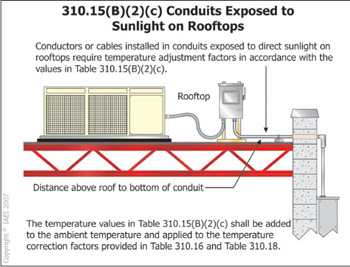
Figure 4. Conductors exposed to sunlight on rooftops
A new requirement in subdivision (c) has been added to Section 310.15(B)(2). In addition, a new companion Table 310.15(B)(2)(c) has been added to this section. To correlate with this change, the existing FPN 2 to Section 310.10 has been deleted in NEC-2008. This new requirement for ampacity correction due to ambient temperature results from extensive study, fact-finding efforts, and collected data that demonstrated valid concerns about excessive heat exposure for conductors and cables installed on rooftops in the sunlight. Full details are contained in the test report entitled Effect of Rooftop Exposure on Ambient Temperatures Inside Conduits, November 2005. The studies clearly warranted new requirements for ampacity correction factors for such installations. In electrical installations of conduit, tubing, and cable that are on rooftops and exposed to the sunlight, temperature value factors in accordance with new Table 310.15(B)(2)(c) are now required to be added, and vary based on the height the wiring method is installed above the roof surface. For example, if a conduit is installed 300 mm (12 in.) above a rooftop in an ambient temperature of 122ºF, then 30º is required to be added to the anticipated maximum ambient temperature in which the conduit is installed. In this case, the value of 152ºF must be used for temperature-correction-factor-application adjustments from the applicable table in 310 (see figure 4).
Revision: 314.27(D) Boxes at Ceiling-Suspended (Paddle) Fan Outlets
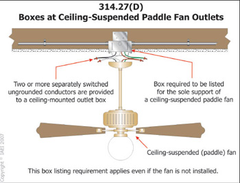
Figure 5. Boxes at ceiling-suspended (paddle) fans
A new last sentence adds specific requirements regarding the type of box that must be installed when two or more switched ungrounded conductors (switch legs) are roughed in to the box. The new requirement calls for a box that is listed for sole support of a ceiling-suspended paddle fan. This requirement applies to all occupancy types as it is currently worded. This affects the rough-in stages of all electrical installations where ceiling-mounted outlet boxes are installed and more than one switch leg is provided to the outlet. It is commonly understood that in many residential occupancies and some commercial occupancies, luminaires are sometimes replaced by a ceiling-suspended paddle fan at some time after the initial installation, but rarely are the proper listed boxes installed to accommodate the fan support requirements in the NEC. This new requirement takes a proactive approach through a rule that should help reduce the number of ceiling-suspended paddle fan installations that would be supported solely by boxes that are not designed or suitable for providing adequate support (see figure 5).
New Article: Article 355 Reinforced
Thermosetting Resin Conduit: Type RTRC
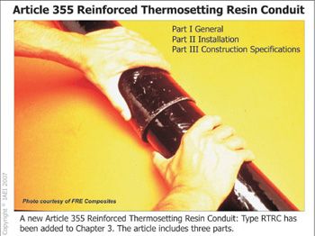
Figure 6. Reinforced thermosetting resin conduit: Type RTRC
Requirements for reinforced thermosetting resin conduit: Type RTRC have been included in the Code as Article 355. In NEC-2002, Article 352, Rigid Nonmetallic Conduit (RNC), included PVC, RTRC, and HDPE products. However, for NEC-2005, High Density Polyethylene Conduit: Type HDPE was separated from these other conduit types and located in new Article 353. This action left two very dissimilar products grouped together as rigid nonmetallic conduit under Article 352, and technically eliminated HDPE as an acceptable wiring method in all applications where rigid nonmetallic conduit was specified. The separation of PVC and RTRC conduit and the change in title to Article 352 and new definition of Rigid Polyvinyl Chloride Conduit in Article 352 are specific to PVC conduit and fittings. Types HDPE and RTRC are covered under separate articles, correcting this situation by better defining the installation and construction specifications for each nonmetallic conduit type. The new Article 355 includes three parts as follows: Part I General, Part II Installation, Part III Construction Specifications (see figure 6).
Revision: Article 382 Nonmetallic Extensions
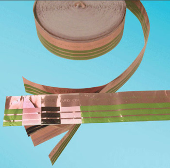
Figure 7. Concealable flat nonmetallic extensions
Article 382 has been revised to incorporate provisions for concealed flat nonmetallic extensions. A new definition of this type of concealable flat nonmetallic extension has been added in 382.2. The article has been expanded to include specific product listing requirements in 382.6. Sections 382.10 and 382.12, covering Uses Permitted and Uses Not Permitted, have been revised and expanded to incorporate requirements and restrictions for concealable flat nonmetallic extensions. A new Part III has been added to Article 382 and provides specific construction specifications for concealable flat nonmetallic extensions. New technologies, consumer electronics devices such as flat panel televisions and custom audio systems, along with ever-changing lifestyles have increased the need for additional power outlets and the desire to place power or lighting outlets where needed to obtain functionality as well as an aesthetically pleasing environment. Often these changes are poorly accommodated through the use of extension cords that are easily damaged, misused and can lead to electrical hazards. This new type of concealable flat nonmetallic extension incorporated into Article 382 provides a safe and reliable alternative for existing occupancies that can reduce the misuse of extension cords, overload power taps, and so forth (see figure 7).
Revision: 406.8(B) Wet Locations
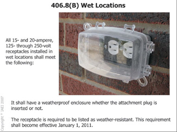
Figure 8. Receptacles in wet locations exposed to the elements
Action by CMP-18 responds to substantiation that demonstrates a need for receptacles installed in these locations to be suitable for the elements they are subjected to over time. The sentences, “The receptacle shall be a listed weather-resistant type. This listed weather-resistant requirement shall become effective on January 1, 2011.” have been added to Sections 408.8(A), 408.8(B)(1), and 408.8(B)(2). Substantiation indicated that deterioration and other detrimental conditions have a negative effect on receptacles, and often result in the receptacle faces becoming brittle and breaking. Even though the NEC has made significant progress in the cover requirements for receptacles installed in wet and damp locations, receptacles are still often exposed to varying degrees of moisture, UV, and impact under detrimental conditions (low and high temperatures). These products have not been constructed or evaluated to being exposed to these conditions. An appropriately listed weather-resistant receptacle (able to withstand the elements) addresses the associated safety hazards and concerns of suitability of electrical products for outdoor use. Statistical data has substantiated the need for a more weather-resilient device in spite of the use of protective covers. The inclusion of the proposed additional text in conjunction with the existing code language would address this dangerous condition and noted failure rates. A new last sentence added to these sections provides device manufacturers ample notice to ensure product availability when the requirements become effective (see figure 8).
New Section: 406.11 Tamper-Resistant Receptacles in Dwelling Unit
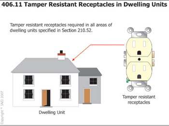
Figure 9. Tamper-resistant receptacles required in dwelling units
Action by CMP-18 on proposal 18-40 results in a new requirement in Article 406 addressing receptacles installed in dwelling units. The new definition of dwelling unit provides clarity for users as to the extent of this new requirement. This new section adds a requirement that all 15- and 20-ampere receptacles installed in outlets required under Section 210.52 for dwelling units be a listed tamper-resistant type. Substantiation provided with the proposal clearly identified a concern about the number of injuries to and electrocution of children when foreign objects are inserted to receptacles. The substantiation provided by The U.S. Consumer Product Safety Commission’s (CPSC) National Electronic Injury Surveillance System (NEISS) indicated that during a 10-year period, from 1991 to 2001, over 24,000 children in the United States were injured when they inserted foreign objects into electrical receptacles. Every year, an average of at least 2,400 children are injured when tampering with electrical receptacles. Patient information is collected from each participating NEISS hospital for every emergency visit involving an injury associated with consumer products. From this sample, the total number of product-related injuries treated in hospital emergency rooms nationwide can be estimated. The number of injuries to children related to insertion of foreign objects into electrical receptacles is significant and has demonstrated the need to require more protection. Tamper-resistant receptacles are presently required in rooms, bathrooms, playrooms, activity rooms, and patient care areas of pediatric wards and provide a level of protection against this type of injury to children. The effect of this change extends the tamper-resistant receptacle requirement to all 125-volt, 15- and 20-ampere receptacles in all areas specified in 210.52 for dwelling units (see figure 9).
Revision: 408.36 Overcurrent Protection
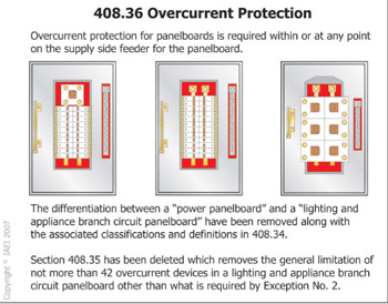
Figure 10. Panelboards no longer limited to 42 overcurrent devices
Sections 408.36(A) and (B) and the associated exceptions have been restructured into one section with three exceptions. Under this revision, the differentiation between power panelboards and lighting and appliance branch-circuit panelboards has been removed. Existing subdivisions (C), (D), (E), and (F) of this section have been re-identified as subdivisions (A), (B), (C), and (D), respectively. Sections 408.34 and 408.35 which included definitions of power panelboard and lighting and appliance branch-circuit panelboard have both been deleted as a result of these revisions to Section 408.36. The revisions to this section essentially remove the 42 overcurrent device limitations for panelboards and also result in requirements that now address power panelboards and lighting and appliance panelboards in the same fashion. The newly created Exception No. 1 is based on the 2005 exception to 408.36(B) which is intended to recognize a long-standing practice of allowing a small panel to be used as service equipment, with large line-to-line loads leaving at this point and a smaller feeder entering the building to supply what formerly was called a lighting and appliance branch-circuit panelboard. The limitations now contained in this exception prevent the extension of this limited practice to what could otherwise become a split-bus panelboard with an unlimited number of overcurrent devices in the future. The six-circuit limit mirrors the customary service limitation contained in 230.71. Exception No. 2 corresponds to the 2005 language at 408.36(A) [see figure 10].
Revision: 422.51. Cord- and Plug-Connected Vending Machines
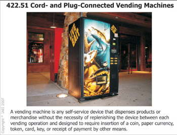
Figure 11. GFCI protection for vending machines
In the NEC-2005 development process, a new section 422.51 was added that requires cord- and plug-connected vending machines that are manufactured or re-manufactured on or after January 1, 2005, to include ground-fault circuit interrupter protection that is an integral part of the attachment plug or otherwise provided in the cord within 300 mm (12 in.) from the attachment plug. The new requirement results in revisions to the product standards [UL 541-2005 (refrigerated) and UL 751-2005] for vending machines. For older vending machines that were manufactured before this new requirement, the protection must be provided by connection to a GFCI-protected receptacle outlet. This new NEC-2005 requirement generated several questions and concerns about what a vending machine really is. Action by CMP-17 on proposal 17-27, results in new language in Section 422.51 that provides users with basic criteria as to what constitutes a vending machine. The additional information should provide the needed clarity for installers and Code enforcement authorities that results in more uniform and consistent application of the protection requirements in this rule. The new FPN following this section provides users with a handy reference to the applicable product safety standard for vending machines (see figure 11).
Revision: 501.10(B)(7) Class I, Division 2 Wiring Methods
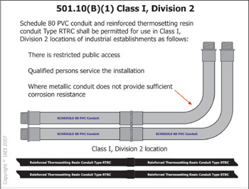
Figure 12. RTRC and schedule 80 PVC in Class I, Division 2 locations
Action by CMP-14 responded favorably to proposal 14-33 to expand the wiring methods listed in 501.10(B)(1) to include reinforced thermosetting resin conduit (RTRC) and schedule 80 PVC conduit. Substantiation provided with proposal 14-33 indicated that there were situations where corrosion concerns for metallic methods could affect the installation. It was also pointed out that there are already current allowances in the NEC (under specific conditions) for nonmetallic wiring methods in Class I, Division 2 locations. The result was the creation of a CMP-14 proposal (14-33a) that incorporates these two nonmetallic wiring methods into this section. This type of wiring in Class I, Division 2 locations is limited to use only in industrial establishments with restricted public access, where the conditions of maintenance and supervision ensure that only qualified persons service the installation, and where metallic conduit does not provide sufficient corrosion resistance. Although this section has been expanded to include Type RTRC and PVC conduit as wiring methods in Division 2 locations, restrictions provided in this new item (7) have inherent limitations on the use of nonmetallic wiring methods in Class I, Division 2 hazardous locations (see figure 12).
New Section: 513.3(C)(2) Aircraft Painting Hangars
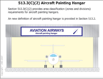
Figure 13. Aircraft painting hangar rules in the NEC
Section 513.3(C) has been revised and restructured into a list format to meet the NEC Style Manual requirements. A new (C)(2) has been added to this section, providing area classification for aircraft painting hangars. Previous editions of the NEC did not include hazardous area classification for aircraft hangars used for painting. NFPA Standard 409-2005 has been revised to specifically separate the hazardous locations near aircraft for aircraft paint hangars from those of general maintenance. Aircraft paint hangars, while constructed like huge paint booths, do not have the same dimensional clearances found in traditional paint booths. The shape of the aircraft creates clearances far greater than that found in any other painting system. This creates a level of safety not found in traditional paint booths and supports hazardous location classification that is less than the entire hangar. The new definition of aircraft painting hangar provides clear descriptive information about what constitutes an aircraft painting hangar to facilitate appropriate application of the area classification boundaries provided in the new provisions in Section 513.3(C)(2). These revisions provide designers, installers, and enforcers with necessary information that establishes the extent of the Class I, Division 2 or Zone 2 locations where aircraft is painted in hangars (see figure 13).
New Article: Article 519 Control Systems for Permanent Amusement Attractions

Figure 14. Control systems for permanent amusement attractions
CMP-15 responded favorably to a proposal to incorporate a new Article 519 in Chapter 5 that addresses control systems for permanent amusement attractions. Previous editions of the Code did not provide rules that could be applied to these types of installations. While Article 525 provides general requirements for electrical installations at carnivals, fairs, circuses, and similar events, it applies only to those entities that are portable. The new article provides specific rules applicable to control power sources and conductors, including associated control wiring in or on all structures that are part of a permanent amusement attraction, as indicated in the scope of the new article. The article is divided into three parts: General, Control Circuits, and Control Circuit Wiring Methods. The new article should provide users with rules that can be applied to these specialized installations and systems that are unique and permanently installed (see figure 14).
New Article: Article 585 Critical Operations Power Systems (COPS)
Figure 15. Critical Operations Power Systems
The new article is the result of work by the NEC Technical Correlating Committee Task Group on emergency and standby power systems for Homeland Security. Code-Making Panel 20 was re-formed for the NEC-2008 development process. The primary assignment from the NEC Technical Correlating Committee for CMP-20 was to develop a new article that addresses power systems or circuits that are critical, and considered vital to remain operational in the event of disruption of power. Recent terrorist events and natural disasters, including the World Trade Center attack, the 2005 hurricane season, most notably Hurricane Katrina, have brought to light the need to assess the adequacy of current requirements in the NEC that address mission critical facility electrical infrastructure protection and reliability. Such systems may be installed throughout an entire facility or may be limited to specific areas depending upon the nature of the operations and where they are to be conducted within a specific facility. An important aspect of proper and consistent application of this new article requires understanding which entities are responsible for determining facilities that qualify for critical operations power systems. The scope of the new article provides guidance about which authority has the responsibility for making these determinations. The new article includes five parts: General, Circuit Wiring and Equipment, Power Sources and Connection, Overcurrent Protection, and System Performance and Analysis (see figure 15).
New Article: Article 626 Electrified Truck Parking Space Equipment
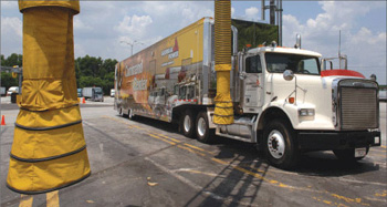
Figure 16. Electrified Truck Parking Space Equipment Photo courtesy of Georgia Power
Action by CMP-12 results in the addition of a new Article 626. This article resulted from the work of the Truck Stop Electrification (TSE) Committee of the National Electric Transportation Infrastructure Working Council (IWC), sponsored by the Electric Power Research Institute (EPRI). The TSE Committee is a multi-industry group of professional volunteers, involving truck manufacturers, TSE designers and implementers, component manufacturers, utilities, and members of the National Association of Truck Stop Operators, Society of Automotive Engineers (SAE), Environmental Protection Agency, Department of Energy, Department of Defense, IEEE, EPRI, and others, working together to develop the TSE infrastructure. Over the past several years, the attention of regulatory agencies and environmental groups has focused on means to reducing truck idling, thereby reducing emissions and fuel consumption. More than twenty states and cities have already adopted legislation to reduce the number of hours a truck idles. Developing a standardized, safe and efficient means of reducing fuel consumption and emissions is the primary objective. This new article provides users with rules that can be applied to electrical installations and systems designed for supplying electrical power and services to trucks while they are parked. This new article includes provisions similar to those that already exist in Articles 550 and 551 that also include requirements for permanent power facilities (see figure 16).
Revision: 700.9(B) Wiring
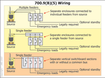
Figure 17. Emergency system wiring separation requirements
The general requirements and concepts behind Section 700.9(B) relate to separation between emergency circuits from other than emergency loads, unless in accordance with the allowances provided in this section. Action by CMP-13 results in a new list Item (5) in Section 700.9(B). This additional text clarifies that the original separation requirements from the source to the loads, or from the source-distribution overcurrent protection to the loads, is to be required unless modified by any of the provisions in items (1) – (5). The revised text will further clarify that it is permitted to supply any combination of emergency, legally required, or optional loads from a single feeder, or from multiple feeders, or from separate vertical sections of a switchboard that are supplied by either a common bus or individually. The use of an overcurrent protective device at the standby source or for the equipment is related to reliability and design. While the new requirements in (5)(b) maintain the highest degree of reliability, the exception to (5)(b) will also permit the use of an overcurrent device at the source or for the equipment. The coordination of the overcurrent protection at the source or for the equipment with the downstream overcurrent protection requirement in this exception will maintain the highest degree of reliability possible while allowing protection for conductors and equipment. The revised text in the main paragraph clarifies that circuits supplying emergency loads are not to be combined in panelboard enclosures with circuits supplying other loads (see figure 17).
New Section: 800.156 Dwelling Unit Communications Outlet
Figure 18. Dwelling unit communications outlet