Based on the response to recent seminars, the topic of medium voltage equipment and installations is one of high interest. This article will provide a brief history of the evolution, as seen by the author, of the industry and give a high-level overview of a few key areas from the product standpoint and terminology.
Not so many years ago (about 30), electrical power distribution equipment rated over 600 volts was generally found only in two places, utility systems and large industrial facilities. In utility systems, the power system is owned and operated by the utility. This system consists of generation from some remote location, high voltage transmission lines, and high voltage distribution lines that end at a transformer, serving premises wiring at a utilization voltage less than 600 volts (see figure 1). Large industrial plants, such as refineries, chemical plants, pulp and paper mills, and steel mills demand large amounts of power to operate. To get this power distributed around the plant economically, distribution voltages are typically over 600 volts. There are some exceptions to the above applications, but these are very few.
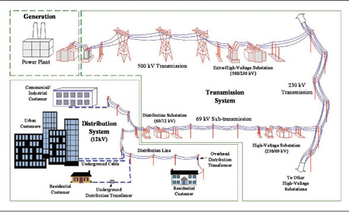
Figure 1. Electrical power distribution system. Graphic concept courtesy of G. Karady and K. Holbert
In the past, facilities having systems over 600 volts were handled by specialists well qualified for the design, installation and operation of these systems. Voltages for these systems were typically in the 5 kV or 15 kV class with utilization levels of 2300 volts, 4160/2300 volts, 12,470 volts or 13,800 volts. One such installation function requiring a specialty skill level is the handling, splicing and terminating of conductors. Traditionally, this was such a specialty that many electrical contractors did not even attempt this work themselves, preferring to subcontract it to other contractors that specialized in this type work.
Today, much has changed. The large industrial plants still have these high voltage systems, but now the voltages found within the plant are much higher. It is not uncommon for main substations operating at 230,000 volts (230 kV) to be owned and controlled by the plant, rather than the utility. Plants in the high-tech industries and others not traditionally thought of as “heavy industries” have primary substations, like in photo 1, rated 115 kV or 138 kV. Going beyond the industrial sector, hospitals, waste water treatment plants, shopping malls, assisted care living complexes, schools (even elementary schools) are being supplied at medium voltage, (commonly in the 5 kV to 15 kV range) and taking advantage of utility rates at primary metering.
There is one large civic/convention center and hotel complex under construction in a major city today that is receiving service at 138 kV and distributing 12.47 kV throughout the complex.
Products have evolved such that, while care must still be exercised, the art of cable splicing or terminating is no longer the specialty it once was. Complete splicing and termination kits have been developed such that qualified electricians can properly complete a splice or termination by reading and following the directions for the kit.
The use of SF6 insulation systems and vacuum interrupters has also increased in recent years. Use of SF6 or vacuum technologies in switchgear and bus structures has allowed an overall reduction in size of the equipment.
In this document, the terms high voltage and medium voltage are used. What do these terms mean and how are they defined? These and many other terms unique to this kind of equipment and installation must be understood before one can begin to properly design, install, maintain, or inspect this equipment. Anyone working with high or medium voltage equipment needs to begin by learning the terminology and avoiding use of trade language or slang.
Low Voltage–per the NEC, this applies to equipment rated and operating at 600 volts or less, with some exceptions. Examples of the exceptions in the NEC include the wire ampacity tables in 310.16 to 310.19 which address conductors rated 0–2000 volts, and Article 250 Part X which addresses systems over 1000 volts. The IEEE standards define low voltage as equipment rated and operating at voltages 1000 volts or less. Because there was very little equipment operating at voltages between 600 volts and 1000 volts, this discrepancy between the NEC and IEEE definitions of low voltage had not caused any real issues until a few years ago. Recently, there have been large numbers of installations of traction power systems that operate between 750 to 850 volts dc. In many jurisdictions, these systems are subject to approval by the local authority. When applying the NEC to these systems, the installer and inspector may be confused as to whether these systems are low voltage or high voltage systems. There may also be similar confusion regarding equipment from overseas manufacturers, which is rated and operated at 690 volts.
The following additional voltage terms and definitions are taken from the IEEE standards so the term and the range of voltage covered can be understood.
Medium Voltage –
greater than 1000 volts and up to 72,500 volts
High Voltage –
greater than 72,500 and up to 230,000 volts
Extra High Voltage –
greater than 230,000 volts and up to 765,000 volts
Ultra High Voltage –
greater than 765,000 volts
There are many other terms that are used and may be the subject of a future article.
When designing, installing or inspecting systems over 600 volts, there are several key aspects that must be considered. These relate to the products used and how they need to be handled as well as some safety points when inspecting. This will be a high-level overview and will focus mainly on the medium voltage systems that are most commonly seen today. This overview definitely will not cover all the points from the NEC, product standards and different field situations, but should provide the reader a glimpse into what can be involved when working with these type systems.
First and foremost, any undertaking on medium voltage equipment needs to be done by qualified people. The NEC definition of qualified is: “One who has skills and knowledge related to the construction and operation of the electrical equipment and installations and has received safety training on the hazards involved.”
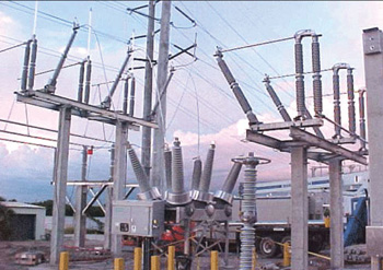
Photo 1. Primary substation rated 115 kV or 138 kV
This definition makes it clear that to be qualified the individual must be skilled and knowledgeable on how the equipment is constructed and how it operates. The individual must understand the installation and system in which it is applied, including the fact that the equipment is medium voltage and not low voltage; so appropriate test equipment is used. There has been more than one case of injury reported in the last few years from an electrician using a low voltage tester (digital multimeter or other tester) to verify that the medium voltage equipment was de-energized, when in fact, it was not. The resulting catastrophic failure of the test instrument in the electrician’s hands caused serious injuries and major equipment damage.
The individual must fully understand the hazards involved with working on or near this equipment, and must be aware of the precautions, safety procedures and levels of personal protective equipment required when exposed to live parts at the applicable voltage level. The requirements in Part III of Article 110 also make it clear that the qualifications for working on or around medium voltage equipment are different than the qualifications for working on or around low voltage equipment.
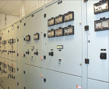
Photo 2. Power distribution equipment commonly called switchgear
Medium voltage installations involve equipment that falls into one of five major categories. These are generators, power distribution equipment (commonly called “switchgear”) such as that in photo 2, conductors or cables, transformers, and utilization equipment.
Utilization equipment that operates at medium voltage is typically some sort of motor-operated equipment such as large pumps (photo 3), centrifugal chillers for air conditioning plants, or large capacity electrode boilers.
For the vast majority of low voltage equipment, product evaluation and certification is conducted using product safety standards from Underwriters Laboratories (UL). This is not necessarily true for medium voltage products. While there are UL standards for medium voltage cables (UL 1072, the Standard for Medium Voltage Power Cables), medium voltage motor control equipment (UL 347 The Standard for High Voltage Industrial Control Equipment and UL Subject 347B, Outline of Investigation for Medium Voltage Motor Controllers, Up to 15 kV), and even motors up to 7200 volts (UL 1004, the Standard for Electric Motors), most products such as switchgear, circuit breakers, fuses, and transformers are investigated and listed for U.S. applications to ANSI/IEEE standards. The standards for switchgear, circuit breaker and fuses are in the ANSI/IEEE C37 series. Specifically, switchgear is classed and is tested to the following standards:
Metal Clad Switchgear –ANSI/IEEE C37.20.2
Metal Enclosed Switchgear –ANSI/IEEE C37.20.3
Subsurface, Vault and Padmounted Switchgear –ANSI/IEEE C37.74
Transformers are covered by the ANSI/IEEE C57 series of standards, with dry type and liquid filled transformers having separate standards within the series.
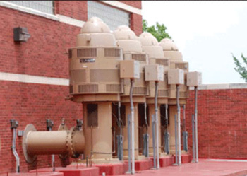
Photo 3. Motor-operated (pumps) utilization equipment
UL has a number of listings in various medium voltage product categories and completes field evaluations on medium voltage equipment using the ANSI/IEEE standards as the basis for the evaluation and certification. Page 30 of the 2007 UL White book provides a quick reference list of those product categories that have UL certifications. Those categories can also be referenced using UL’s Online Certification Database atwww.ul.com/databaseby entering the four-digit category codes for the type of equipment at the category code search prompt. Some of these category codes are as follows:
Overcurrent Protection and Switchgear
Fuses, Over 600 volts (JEEG)
Circuit Breakers and Metal-clad Switchgear Over 600 volts (DLAH)
Circuit Breakers, Medium Voltage, Classified for Use in Specified Equipment (DLBC)
Circuit Breaker Switchgear, Metal Enclosed, Over 600 volts (DLBK)
Switchgear, Gas Insulated Type, Over 600 volts (WVEK)
Switches, Load Interrupter and Isolating, Over 600 volts (WIQG)
Transfer Switches (WPTZ)
Automatic Transfer Switches Over 600 volts (WPYC)
Power Distribution Equipment and Devices
Grounding Equipment, Neutral Grounding Devices, Over 600 volts (KDZC)
Surge Arresters 1000 volts and Higher (VZQK)
Transformers, Distribution, Dry Type, Over 600 volts (XPFS)
Transformers, Distribution, Liquid-filled Type, Over 600 volts (XPLH)
Unit Substations Over 600 volts (YEFV)
Wiring Methods and Devices
Busways, Metal Enclosed, Over 600 volts (CVZW)
Metal-clad Cable (PJAZ)
Metal-clad Cable Connectors, Type MC (PJOX)
Cable for Use in Hazardous Locations (PJPP)
Metal-clad Cable Classified in Accordance with
UL 1569, with Metric Conductor Sizes (PJPJ)
Medium-voltage Power Cable (PITY)
Medium-voltage Cable Classified in Accordance
with UL 1072, with Metric Conductor Sizes (PIVW)
Power and Control Tray Cable (QPOR)
Power and Control Tray Cable Connectors (QPOZ)
Wire Connectors and Soldering Lugs (ZMVV)
Thermoset-insulated Wire (ZKST)
Control Equipment
Motor Controllers (NJOT)
Motor Controllers Over 1500 volts (NJHU)
Motor Controller Accessories Over 1500 volts (NJIJ)
Motor Controllers Over 1500 volts for Use in
Hazardous Locations (NRAA)
Power Conversion Equipment, Medium
Voltage (NJIC)
Pump Controllers, Fire, Over 600 volts (QZGR)
There are some cases where there are several standards for the same product. For example, there are cable standards published by UL, AEIC and ICEA. This multiplicity of standards sometimes creates interesting situations where there are slight differences in requirements between standards. For example, the insulation thickness for 15 kV, 133% insulation level, solid dielectric type cable is 215 mils in one standard but is 220 mils in another standard. These differences may not seem like much until you consider that someone making terminations that require a tight fit over the insulation now has to deal with this potential difference. What is normally found is the cable manufacturers will build the cable with an insulation thickness of 220 mils since that would meet the requirements of both standards and allow for standardized terminations.
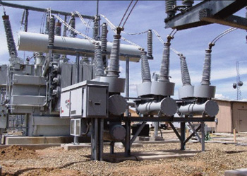
Photo 4. Installation of typical outdoor medium voltage circuit breaker
The IEEE standards are typically written from a performance and testing perspective and do not have the degree of prescriptive requirements that are typical of UL standards. For example, the standards for medium voltage metal-clad or metal-enclosed switchgear do not establish firm spacing dimensions between uninsulated live parts, such as busbars of different phases or uninsulated phase conductors to grounded enclosures. The spacing of any manufacturer’s equipment is proven by specific design testing including Basic Impulse Level (BIL) and Dielectric Withstand testing. This may result in different manufacturers actually having different designs and spacings for their equipment. These differences may make it very difficult to add a section to an existing lineup of medium voltage switchgear where the added section is from a different manufacturer than the original switchgear.
When equipment is examined in the field, the acceptability of spacings between live parts, and to ground, cannot be determined by visual inspection or measurement alone, there must be some test data to back up the design. For installations subject to the requirements in the NEC, since the field wiring is not subject to this testing, Table 490.24 provides prescriptive minimum spacing depending on voltage level, the BIL rating of the equipment and the installation location (indoor or outdoor). In addition, consideration must be given to the expected level of contamination, which can lead to tracking and flash over. The spacings provided in the NEC are not to be applied to equipment that has been tested and certified, and inspectors need to be careful not to apply NEC requirements to internal construction of equipment.
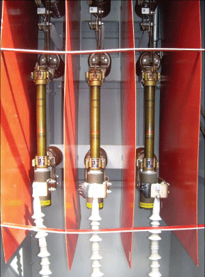
Photo 5. Expulsion fuses 15 kV switch
Another difference between low voltage and medium voltage equipment is the use of circuit breakers. With respect to low voltage, a circuit breaker is a single device, having one, two or three poles, that provides a means for switching and also has overcurrent protection within the device. Typically, the contacts of low voltage circuit breakers use air as the interrupting medium. A medium voltage circuit breaker may have an interrupting medium of air, vacuum or SF6 gas. A medium voltage circuit beaker is essentially a switching mechanism with a mechanical means to open and close (springs, pneumatic, solenoid) and electrical operators to initiate an open or close sequence. Photo 4 shows the installation of a typical outdoor medium voltage circuit breaker.
Since medium voltage circuit breakers normally do not contain integral overcurrent protection, the “brains” that provide the desired overcurrent protection are provided from separate devices, which typically include current transformers and protective relays. One result of this is that there are only a few circuit breaker ratings, typically 1200, 2000, 3000 and 4000 amps. This rating is the maximum current the circuit breaker can carry continuously. The breaker also has short time and interrupting ratings that are in excess of the continuous rating and these are identified on the nameplate.
To establish the current rating of the circuit and to provide overcurrent protection to meet a design or Code requirement, the designer must specify a current transformer (CT) of the appropriate ratio, (such as 200:5) and a protective relay with a specific pickup value. The combination of the CT ratio and the relay setting determine the circuit capacity. For example, with a CT ratio of 200:5, and a relay setting of 4 amps, the circuit protection then equates to a circuit rating of 160 amps. In this example, adjusting the protective relay pickup setting from 4 to 5 amps provides a circuit ampacity of 200 amps.
The construction and application of fuses also vary between low and medium voltage fuses. While low voltage fuses, applied within their rating, are not intended to expel any gases or hot particles when interrupting an overcurrent, medium voltage fuses can be of the non-expulsion type or an expulsion type (see photo 5). While non-expulsion type fuses are sealed, similar to typical low voltage fuses, expulsion fuses intentionally expel gases that form within the fuse body during fault interruption, typically through a muffler assembly. These gases are very hot and highly conductive. Because of this, the designer and installer must ensure that no other equipment, such as power cables, control wiring, or space heaters are placed in the area or path where these gases are to be discharged. Other equipment that is in the path will be damaged and may result in a cascading fault by the conductive gases degrading the electrical insulation and initiating another fault. Manufacturers’ instructions and layout drawings must be followed to keep these areas clear of conduit entries and of any auxiliary type equipment in the switchgear.
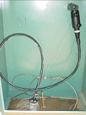
Photo 6. Conduit enters the bottom of the enclosure just to the left of center.
Another point regarding manufacturers’ drawings and instructions for cable entry points needs to be made. Shielded medium voltage cables have a minimum-bending radius of 12 times the outside diameter per NEC 300.34. Manufacturers will provide the locations for conduit to enter enclosures so that the proper cable-bending radius can be complied with. Often, this fact is ignored at the time of laying out the conduit in the trenches and then it all gets set in concrete. Bending cables to less than the required minimum-bending radius during or after installation may create a failure point in the cable. In photo 6, a conduit enters the bottom of the enclosure just to the left of center. The cable forms a complete loop and then ends in a load break elbow termination. The 12x rule for this cable would require a minimum-bending radius of 12 inches, or for the full loop a diameter of 24 inches. This enclosure has a 36-inch interior width. As can be seen, this loop has a bending radius of less than the minimum allowed, which creates excessive strain on the layers of the shielded cable that form the complete insulation system. In this case, the improper installation also put sideways pressure on the load break elbow and bushing that also could lead to failure.
In summary, medium-voltage and high-voltage systems are becoming more common in many areas not seen in the past. Personnel that are involved with these systems, including installers, maintenance staff, or inspectors, must be qualified to work on or around this type equipment.
The products have evolved and technology continues to develop with newer designs and products. More electricians are completing installations of medium and high voltage equipment and conductors, so they need additional training in handling these systems and the various products involved. Inspectors now must understand more requirements in areas where they may have little or no experience, but are still responsible to determine acceptability of the installation. Product standards exist for nearly all medium voltage and high voltage products on the market today. Many medium and high voltage products are already available as listed products. Under certain conditions, medium or high voltage products, which are not listed, may be field evaluated to assist the AHJ in granting final approval. In the case of field evaluations, all the applicable product standards and manufacturers instructions need to be followed, in addition to the Code requirements to ensure proper installations.