The PV Array—Mechanical Considerations
The PV array consists of individual PV modules attached to a mechanical frame, usually attached to the structural members of the roof in a typical rooftop-mounted residential utility-interactive PV system. Although not an electrical-code issue, some attention must be given to the attachment of the PV array to the building structure.
Most roofs in recent years have been built using span tables in the building codes or using trusses designed by professional engineers. PV arrays may add up to 4–5 pounds per square foot of dead weight to the roof structural members, and that weight will be concentrated through the rack mounting feet. Also, because the PV array is mounted above the roof some distance (zero to six inches or more), the roof may be subjected to both uplift and down-force wind loadings—again concentrated through the mounting feet of the rack. If the roof has several layers of old shingles under the array, the structural limit of the roof may be approached. Leaving as many as two layers of old shingles in place is a common practice during re-roofing, so we can assume that the basic roofing structure has a safety factor allowing the extra load of old shingles or the PV array, but possibly not several layers of shingles and a PV array.

Photo 1. Array rack attachment point – used in dry climates
Array racks must be attached to the structural elements of a roof (trusses or rafters), and this will require penetrating the roofing surface material in a manner that is weatherproof for the life of the PV array or the life of the roof—whichever is shorter (see photo 1).
Stainless steel hardware is usually used to connect the modules to the racks. Galvanized hardware is frequently used to bolt the racks to the roof. In both cases, corrosion resistance is a must in most climates.
PV Array—Electrical Requirements

Photo 2. Module with attached cables and connectors
Electrically, the PV array consists of PV modules connected in series using exposed single-conductor cables with “finger safe” connectors (see photo 2). The conductors are typically USE-2 as allowed by NEC Section 690.31. In the 2008NEC, a new PV Wire (a.k.a. PV cable, photovoltaic wire, or photovoltaic cable) is also allowed. This conductor is a “super” USE-2 that has a thicker jacket (the conduit fill tables cannot be used), passes a 720-hour accelerated UV test (is marked Sunlight Resistant), and has the flame and smoke retardants of RHW-2. It can be used under and within the PV array for the module interconnections and in raceways in other locations. This new cable will soon be appearing on all modules because it facilitates the use of ungrounded PV arrays and transformerless inverters (lower cost, less weight, higher efficiency) (NEC690.35).

Photo 3. Modules in landscape orientation
Although the electrical connectors attached to the ends of the module cables are “finger safe” when new, if they are opened under load, the dc arc may damage the insulation and the connectors may then pose a shock hazard. Therefore, there are new requirements in 690.33 for locking connectors in the 2008NEC. A tool will be required to open these locking connectors. They will also soon be appearing on most, if not all, PV modules, although they are only required when the PV array wiring is operating above 30 volts and is readily accessible (690.33).
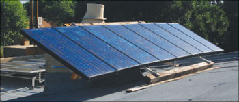
Photo 4. Modules in portrait orientation
Another 2008NECrequirement that applies to readily accessible PV source and output circuit conductors operating at over 30 volts is found in 690.31(A). These conductors must be installed in raceways. Unfortunately, as mentioned above, most PV modules do not have junction boxes with knockouts that would accept a raceway. They come with permanently attached exposed, single-conductor cables and connectors with no provision for attaching a conduit or other raceway. Fortunately, most residential rooftop PV arrays are not readily accessible. A few manufacturers can provide conduit-ready modules on special order, but many module manufacturers have no such option.
The solution, as noted in the 2008NEC Handbook, is to make this wiring not readily accessible by placing some sort of barrier behind the modules that prevents the wiring from being touched without removing the barrier. Fences with locked gates may not be a solution, because a basic maintenance requirement for the readily accessible ground-mounted PV array is keeping the grass mowed—a task usually done by people not qualified to be near PV or other electrical systems.
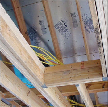
Photo 5. Pipe clamp used to secure module conductors
The conductor leads attached to the modules are 40 inches long or longer to allow the series connection of modules when they are mounted in a landscape orientation (see photo 3). When the modules are mounted in portrait orientation (see photo 4), the excess lengths of conductors must be securely fastened against the module racks to resist abrasive damage due to wind, sleet, and ice. Many use plastic cable ties, but unless they are of very high quality, they may not last the required 40 years or more when exposed to the extremes of heat and ultraviolet radiation from sunlight. Some people use a stainless steel pipe clamp (loop strap) with an EDPM insert (see photo 5).
Section 690.74(D) requires that the PV array metal surfaces be connected directly to earth via a separate grounding electrode. This requirement provides a greater degree of lightning protection for PV systems than other Code requirements provide. This new requirement is in addition to the normal equipment-grounding conductors that run with the circuit conductors and which are connected to earth (grounded) at locations remote from the PV array. If the array is on the same building that contains the inverter and the existing ac grounding electrode, then the array may be connected directly to that electrode and a separate electrode is not required. If the connection to an existing electrode requires a horizontal extension greater than six feet from the closest earth contact point, a separate electrode is required. This new array-grounding electrode does not have to be bonded to any other electrode.

Photo 6. Grounding a metal roof -Oops, outdoor rated lug and wire needed
Module grounding has been discussed recently in previous articles and will not be covered here in any detail. Suffice it to say that the module frames must be effectively grounded, and that is not always easy with aluminum frames and copper conductors. Those single-conductor exposed module wires are bound to touch the roof, if not on initial installation, sometime over the life of the system. The racks must also be grounded, and if the PV array is mounted on a metal roof, that metal roof should be grounded (see photo 6). Rodent damage and abrasion could very well cause the roof to be energized (see photo 7).
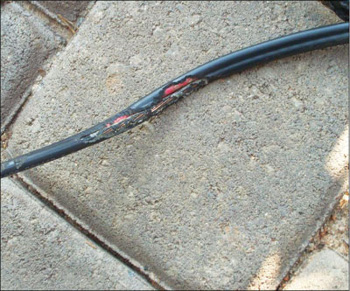
Photo 7. Rodent-damaged conductors
The single-conductor exposed wiring (USE-2 or PV Wire) is allowed only in the near vicinity of the PV array to interconnect the modules and to return the end of the string conductor to the origination point of the string wiring. At this point, the exposed wiring must transition to one of the more common wiring systems found in chapter 3 of the Code. Typically, this will be some form of conduit such as EMT. If the array output conductors penetrate the surface of the structure before reaching the first readily accessible dc PV disconnecting means, then they must be in a metal raceway where inside the structure. Metal raceways include the rigid metal conduits and flexible metal conduit (FMC), but do not include metallic cable assemblies like Type MC and Type AC cables. The transition fitting keeps water, dirt, rodents, and other material out of the conduit. A rain head or a cord grip might be used (see photo 8).
Temperature Corrections

In most locations in the United States, a 75 degree C temperature correction factor is suggested for conductors near PV modules that are mounted roughly four inches or less from a surface like a roof. The distance in not exact and is normally measured from the back of the module frame to the surface. Four inches or less is insufficient clearance to allow cooling air to flow behind the modules mounted in an array.
If the air space behind the modules is greater than four inches, then a 65 degree C temperature-correction factor is suggested. Again, these are not hard and fast numbers, and the individual installation location and microclimate (Death Valley or Nome) may affect them.

Photo 9. Conduits on hot roof
Conductors in conduit on roofs (and possibly elsewhere) in sunlight are also exposed to solar heating, and 310.15(B)(2) in the 2008NECprovides the temperature additions above the expected average high temperatures (see photo 9). These temperatures apply not only to PV systems but any conduits on the roofs of buildings exposed to sunlight. In many cases, where the high average temperatures are in the 40–45 degree range and the conduits are close (1/2″ or less) to the roof, again a 65–75 degree C temperature correction factor applies. Those PV circuit conductors are going to be delivering energy for the next forty years or more, so we really need to carefully apply these temperature correction factors to ensure that the insulation does not suffer premature degradation.
In the next article we will move away from the PV array and on to other parts of the system.
For Additional Information
If this article has raised questions, do not hesitate to contact the author by phone or e-mail. E-mail: jwiles@nmsu.eduPhone: 575-646-6105
A color copy of the latest version (1.8) of the 150-page, Photovoltaic Power Systems and the 2005National Electrical Code: Suggested Practices, published by Sandia National Laboratories and written by the author, may be downloaded from this web site: http://www.nmsu.edu/~tdi/Photovoltaics/Codes-Stds/Codes-Stds.html
The Southwest Technology Development Institute web site maintains a PV Systems Inspector/Installer Checklist and all copies of the previous “Perspectives on PV” articles for easy downloading. Copies of “Code Corner” written by the author and published in Home Power Magazine over the last ten years are also available on this web site: http://www.nmsu.edu/~tdi/Photovoltaics/Codes-Stds/Codes-Stds.html
The author makes 6–8 hour presentations on “PV Systems and the NEC” to groups of 40 or more inspectors, electricians, electrical contractors, and PV professionals for a very nominal cost on an as-requested basis. A schedule of future presentations can be found on the IEE/SWTDI web site.