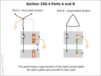
If you were to open an unopened jar, does that jar still qualify as “unopened”? No one would argue the fact that the moment I lock an unlocked door, that door is no longer “unlocked.” I must confess that this author has yet to come across an uneaten piece of cake and left that cake “uneaten.” So why do we consider an ungrounded system “ungrounded” when we are required to establish and connect a grounding electrode system to that ungrounded system? There seems to be a great misconception in both the installation and the enforcement of ungrounded systems as to the requirements for establishing a grounding connection at an ungrounded system. The fact of the matter is that there is nothing “ungrounded” about an ungrounded system. We are required to establish a grounding electrode system at the first means of disconnect to put the cabinets and other metallic equipment at earth’s voltage potential. Then we extend that grounded connection to the last point of the system through our equipment grounding conductors (see the definition of “grounded” and “bonded”). This equipment grounding connection is also the path we provide for clearing any ground faults likely to be imposed. Without a grounding electrode/equipment grounding system at this ungrounded system, we would have to rely on the earth as our fault return path which is prohibited by 250.4(A)(5) for grounded systems and prohibited for ungrounded systems by 250.4(B)(4). The component that is missing from an ungrounded system compared to a grounded system is the intentionally grounded conductor.
Ungrounded Systems
To Ground or Not to Ground
Electrical Systems Operated Ungrounded
Electrical systems that fall outside the requirements for grounding in 250.20 are sometimes operated ungrounded. At times, the facility owner or engineer or a combination of the two will collectively choose to operate electrical systems ungrounded. These systems usually are found in industrial or agricultural applications and are often rated either at 240-volt or 480-volt, three-phase, three-wire systems. Some higher voltage systems are also used in heavy-industrial applications. Where ungrounded systems are installed, the engineering decision is often based on an effort to obtain an additional degree of service continuity while providing equal and effective means for safety of equipment by the use of ground-fault indicator equipment.
Typical systems that are operated ungrounded include:
- 240-volt, 3-phase, 3-wire, delta-connected
- 480-volt, 3-phase, 3-wire, delta-connected
- 2300-volt, 3-phase, 3-wire, delta-connected
- 4600-volt, 3-phase, 3-wire, delta-connected
- 13,800-volt, 3-phase, 3-wire, delta-connected
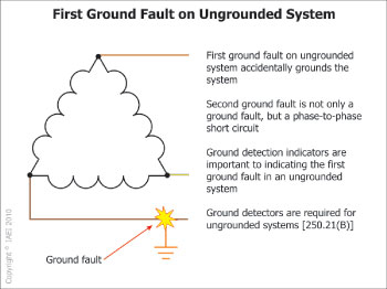
Since the system is ungrounded, the occurrence of the first ground fault (not a short circuit or line-to-line fault) on the system will not cause an overcurrent protective device for the service, feeder, or branch circuit to open or operate. This fault does, however, ground the system but usually accidentally and through ineffective means (higher impedance) and in unspecified and uncontrolled locations. In essence, this system accidentally becomes a corner-grounded delta system. There will be little, if any, current when this first ground fault occurs.
When an ungrounded system with one ground fault experiences a second ground fault on a different phase, the result is a phase-to-phase fault on the system. This will usually cause one or more overcurrent protective devices to open or operate, provided there is adequate current in this path. A major concern for this type of system happens where the first and second faults are located some distance apart. Often, these faults are from line-to-conduit or metallic enclosures, such as wireways, pull boxes, busways or motor terminal housings in different parts of the plant. Where this occurs, a relatively high-impedance path for current is often established. In some cases, a great deal of heat along with arcing and sparking is produced along this fault path due to loose connections or inadequate bonding. Every conduit coupling and locknut connection to enclosures in the fault-current path must be tight to provide an adequate and low-impedance path and to reduce this arcing and sparking.
It is important for safety reasons and for system continuity that maintenance personnel locate and eliminate ground faults when first identified on ungrounded systems. This should be done as soon as practical and especially before the second ground fault on a different phase occurs on the system. These ground faults are usually detected through a ground detection indicator system required by 250.21(B) for systems that are permitted to be ungrounded.
Ground-Detection Indicator Systems

Ground Detectors
In the past, ground detector lights or neutralizer or “potentializer” plugs were installed to indicate that a ground fault had occurred on the ungrounded system. The 7½-watt indicator lights are connected to the lines through 18,000-ohm resistors. A tap is made to each resistor to give 120 volts to the lamp. The lamp burns until its phase goes to ground, at which time there is no or little potential across the lamp and it stops glowing, thus identifying the faulted phase. More modern types of ground detection indication equipment are available and offer the added benefits of no system ground connection, not even through a resistor as was the case in the older ground detection light systems. These systems are typically equipped with transformers (windings) between the indication circuit and the ungrounded conductors of the system.
Ground-fault indication is intended to alert the maintenance personnel to the problem so the ground fault can be corrected during hours when the plant is not operating. The plant can continue to operate with one-phase grounded, thus preventing costly production downtimes. In some cases, downtime in production plants can cost thousands of dollars per minute.
Ungrounded System Problems
An ungrounded system exists only in theory, in a laboratory or at the electrical distribution transformers hanging on the pole before connection to the plant electrical system. In the real world, ungrounded systems having insulated conductors installed in metallic enclosures are grounded to varying degrees through the distributed leakage capacitance of the system. Physically, a capacitor exists whenever an insulating material separates two conductors that have a difference of potential between them.
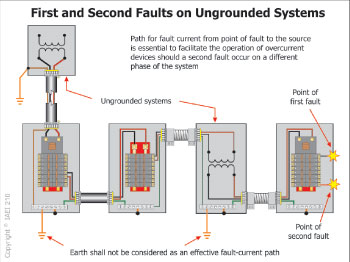
Figure 3. Presence of a second ground fault on an ungrounded system
When any conductor is installed in close proximity to grounded metal, there is a capacitance between them that is increased as the distance between the conductors is reduced. In 600-volt systems, the two greatest sources of capacitance to ground are conductors in metal conduit and windings, such as for motors and transformers. In both cases, conductors are separated from grounded metal by fairly thin insulation. The capacitance to ground is known as the leakage capacitance, and the current from the conductors to ground is known as the leakage current or charging current. This capacitance is distributed throughout the electrical system but electrically acts like it is a single, lumped capacitance.
- Disadvantages of operating systems ungrounded include but are not limited to the following:
- Power system overvoltages are not controlled. In some cases, these overvoltages are passed through transformers into the premises wiring system. Some common sources of overvoltages include: lightning, switching surges and contact with a high-voltage system.
- Transient overvoltages are not controlled, which, over time, can result in insulation degradation and failure.
- System voltages above ground are not necessarily balanced or controlled.
- Destructive arcing burndowns can result if a second fault occurs before the first fault is cleared.
- Ungrounded systems have the characteristic that they are subject to relatively severe transient overvoltages. Such overvoltages can be caused by external disturbances as well as internal faults in the wiring system and easily can reach a value of five to six times normal voltage. An actual case involved a 480-volt ungrounded system. Line-to-ground potentials in excess of 1200 volts were measured on a test meter. The source of the trouble was traced to an intermittent or sputtering (arcing) line-to-ground fault in a motor starting autotransformer. These faults are not uncommon on 480-volt ungrounded systems. During the two-hour period when this arcing fault existed, between 40 and 50 motor windings had failed.
Circuit-switching operations can also be responsible for the creation of transient overvoltages in ungrounded systems. These generally are of short duration and typically reach only two to three times nominal system voltage.
Experience has shown that these overvoltages that easily reach several times the system voltage can cause failure of insulation at locations on the system other than at the point of the fault and can result in future system failures. This often occurs at a system weak point such as in a motor or transformer winding.
Locating the ground fault can be troublesome. While it is easy to spot a ground fault on a one-line diagram, locating it in a plant with a complex electrical system can be much more difficult, unless sophisticated ground-fault detection equipment has been installed. The first step is to open the feeders one at a time and observe the ground detection indicator. After finding the feeder with the ground fault, branch circuits are disconnected, one at a time, until the offending circuit is located. A significant loss of plant operation time can occur during this process. This is contrasted with a grounded system where only the offending equipment is taken off the line by the circuit overcurrent protective devices.
Often, overcurrent devices are set above the current level of the fault in ungrounded systems. When arcing faults occur, destructive burndowns of electrical equipment can result. The arcing fault releases a tremendous amount of energy such that conductors and metal enclosures in the vicinity are destroyed.
When the first ground fault occurs on a 480-volt ungrounded system, the other conductors of the system rise to a level of 480 volts-to-ground. This presents an additional risk of shock to operation and maintenance staff. This can be contrasted to a 480Y/277-volt grounded wye system where the voltage to ground does not exceed 277 volts while the phase-to-phase voltage is 480 volts (even under ground-fault conditions).
Conclusion
Where grounding of the electrical system is optional, the advantages and disadvantages of grounding must be carefully weighed by the plant owner or electrical designer to make the best decision. In the long run, greater service continuity may be obtained with grounded systems rather than ungrounded ones. Faults can be isolated to the feeder or circuit affected and cleared without disrupting the entire system. This is obviously a major consideration if the equipment or circuit affected is critical to the plant operation. This has to be balanced against the ungrounded system’s tolerance of the first line-to-ground fault but with possible deterioration of conductor insulation from transient overvoltages and possible serious damage caused by a second ground fault on the system.
What are you waiting for?
Regardless of whether a grounded or ungrounded system is employed, both systems will be grounded. Don’t let the term “ungrounded” fool you. As we have discussed in this article, there is nothing “ungrounded” about an ungrounded system. Relax and have another piece of cake.
Reference
Some of this article was derived from IAEI’s Soares Book on Grounding and Bonding. If you would like more information on grounded and ungrounded systems, refer to this informative IAEI text.