This is the part of the NEC where new code students often start to become confused. It is essential to clearly explain the difference between grounded and grounding, and then find a way to etch this into the student’s mind so he or she will not confuse or misuse the terms. Therefore, we will go into detail to clearly identify the difference between the two terms.
First, let’s start with a term that is not included in Article 200, and that would be grounding conductor. This term has been deleted in the 2011 Code since it was a term that is more specifically defined by equipment grounding conductor (EGC) and grounding electrode conductor (GEC). The EGC by definition in Article 100 is “the conductive path(s) installed to connect normally non-current-carrying metal parts of equipment together and to the system grounded conductor or to the grounding electrode conductor, or both.” So what does that mean? It means the EGC acts as a bonding means between all the equipment enclosures and any other metallic non-current-carrying parts of the electrical system and connects those parts to the grounding system. As you can see, these terms can appear to overlap and this is about the point where I often get blank stares from those I’m teaching.
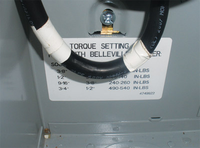
Photo 1. Re-identification of grounded conductor for conductor 4 AWG and larger
Re-identification of grounded conductor for conductor 4 AWG and larger
To break it down further, let’s start with this concept. The EGC is our safety line, meaning that this path (it could be a conductor or other means) is the way for any current to safely return to its source so our protective equipment can do its job and shut down the origin of the power. So during this discussion we refer to the EGC as our safety line or safety net. I need to point out that this path does not carry current under normal conditions, only in the event of a fault.
I can’t stress enough the importance of making sure our EGCs are thoroughly inspected and completely made up on what we call the rough inspection. The reason for this is that when the inspector goes back for the final inspection, all the devices are installed and most covers are in place, so it’s too late to check these connections. Also, in an electrical system everything will work just fine in almost all of our utilization equipment, with or without a proper ground. As long as the hot (ungrounded) conductor and the neutral (grounded conductor) are working, we will never know there is a problem with the EGC until something goes wrong and the fuse or breaker won’t open the circuit. Now if there is a problem with the hot or neutral, naturally you’d have your electrician fix the issue; but because the absence of a grounding connection doesn’t prevent the operation of whatever is connected, no one will ever troubleshoot or correct this condition until it is too late.
So let’s discuss how to identify a grounded conductor. By definition, it is “a circuit conductor that is intentionally grounded.” The idea of grounding a circuit conductor is at times a hard concept to grasp. To a new student of the Code, the first thought that comes to mind is that when we ground something we create a fault condition, which means some form of spark or arc creation. However, we do intentionally ground certain conductors in certain types of transformer connections, as discussed in the previous article. Generally, when we have a grounded conductor we have created what we call a “neutral” conductor. The neutral allows us to create 277 volts on a 480-volt system and 120 volts on a 208- or 240-volt system. Please note that we have grounded circuit conductors which are not neutrals; however, this is not the most common application of a grounded conductor, and is generally used only in large industrial locations which are not the focus of our goal of reaching the combination inspectors. We also have neutrals that carry only the unbalanced current in systems and that can affect whether they are considered current-carrying conductors. It is important to understand the use of the grounded or neutral conductor in each type of system. For the purpose of discussion in this article, we’ll consider our grounded conductors to be neutrals unless stated otherwise.
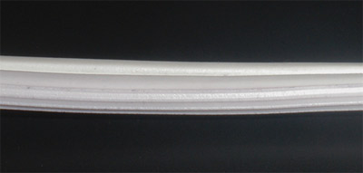
Photo 2. Close-up of lamp cord showing the identification ridges
In Article 200.2 we find that grounded conductors where insulated (and generally they are insulated) must also have the same insulation properties as the ungrounded conductors. Also mentioned is that the continuity of the grounded conductor can’t be dependent on a connection to a metallic enclosure, raceway, or cable armor
The Code imposes certain limitations on neutrals, including that they can only be used for one branch circuit or one multiwire branch circuit, unless specifically allowed elsewhere in the Code. The reason for this is to prevent overloading of the neutrals. One basic item we need to mention here is that neutrals and grounded conductors usually don’t have any overcurrent protection, so if one gets overloaded it will not open a fuse or breaker; it just simply burns up trying to carry the overloaded current. I often ask students if they have ever seen a panel where the white neutrals have started to change colors, turning a light beige or brown. This discoloration is a result of the insulation deteriorating due to overheating from carrying too much current. So how do we prevent this? By making sure we use one neutral per circuit conductor or multiwire circuit. Remember that a multiwire branch circuit is a circuit where the ungrounded (hot) conductors are on different phases, and the neutral, in this case only, carries the unbalanced current of the different phases.
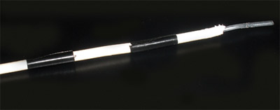
Photo 3. A 12 AWG conductor from a cable assembly re-identified as a white conductor for a switch leg
As you can see so far, the grounded conductor is a pretty specialized part of the circuit, so we need to make sure we have a unique yet consistent method of identification for these. In 200.6 we have the details for identification: any conductor smaller than 4 AWG must have a continuous outer finish of white or grey, or three continuous white stripes. This section of the Code gives us a few other options, but most times you will see that it is just white or gray. You may ask, why two different colors? The reason for this is there are times when we have multiple voltages within the same facility, and when these different systems occupy the same raceway, cable, box, gutter or other enclosure as mentioned in 200.6(D), we have to differentiate between the grounded conductors of one voltage system (such as 120/208) and the other system (such as 277/480). This is done by deciding what the colors will be for each system and then labeling the equipment with the colors selected for the respective voltage. Once the color scheme is decided, the same scheme must be followed throughout the facility.
So what do we do with conductors 4 AWG and larger? We can again have the continuous white or gray outer finish or three white stripes, and it has become fairly common for manufacturers to produce larger size wire with factory marked colors. The other method is that in large wire sizes we may just have black insulation, and for identification of these larger conductors the electrician may field mark them at their termination points and any access points. This marking must encircle the conductor so we can see it from any angle. This is generally accomplished by using colored electrical tape in white or gray. This tape is often referred to as phase tape (see photo 1).
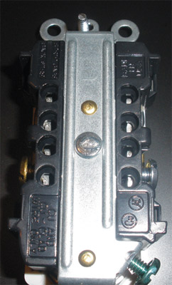
Photo 4. Receptacle showing one screw a darker brass color and one screw a silver or whiter color for identification of the grounded conductor
Usually after I’ve gone over the identification of grounded conductors, I ask the question, How is the grounded conductor of a two-wire appliance of lamp cord identified? I usually get a variety of responses, then I ask the students to read 200.6(A) which states fixture wire will be identified according to 402.8 This article then refers you to 400.22, and in (F) we find our answer which is identification by ridges on the grounded conductor. At this point in the class, we pass around a piece of lamp cord so the students can see and feel what we mean (see photo 2). Also, they have just had the great experience of a good code chase, which sends you here and there to actually get to the final answer.
The next question that comes up is Why do we use a white conductor on switches in residential wiring with cable assemblies? In 200.7(C), we have a provision which allows the white or gray conductor to be used for other than a grounded conductor on circuits of 50 volts or more under certain conditions. When using a cable assembly that has two insulated conductors and a ground, there are usually three conductors: black insulated, white insulated, and a bare ground. You are allowed to use one cable to go to a switch, where one wire will be the ungrounded feed to the switch and the other will be the ungrounded switch leg back to the light. You are allowed to do this when you re-identify the white with a permanent method such as marking (phase) tape, painting or other effective means. I will caution you not to make this harder than it is. I’ve seen instances where the electrician has tried to cover every square millimeter of wire with white tape, and in some conditions the tape just doesn’t stay in place when wrapped this way. The result is loose tape inside the box and often it just falls off. A couple of simple wraps of black tape around the re-identified white conductor is all that is needed (see photo 3).
We’ve talked about identification of the conductor itself, now how do we identify the terminals of devices? The requirements in 200.9 and 200.10 tell us how to identify the grounded conductor termination points. We will cover a few of these in detail, but the first basic rule is that the grounded conductor point of attachment shall be substantially white in color. This is no problem for cord caps as they have a nice white dot showing the grounded conductor. On some items, the manufacturer will actually print or emboss the word “white” near the termination point. On receptacles, the manufacturer also identifies the screw by making it a different color. For instance, the hot or ungrounded conductor would be terminated on a screw which is a brass color, and the grounded, neutral screw would be more of a silver color, which signifies it as a whiter color (see photo 4).
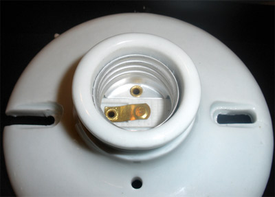
Photo 5. Keyless fixture which clearly shows the screw shell
The next item we discuss for grounded conductor identification is screw shells. So, naturally, I ask everyone, what’s a screw shell? This is one of my favorite questions, as I have yet to have any non-electrical people answer this question correctly. A screw shell is the part of a light fixture where you screw in the lamp (see photo 5). It has a center contact, which matches up to the very tip of the screw-in lamp, and the outer shell which actually has the threads in the shell. Now we have to discuss the significance of connecting the proper conductor to the screw shell. We have to connect the grounded conductor to the shell. If we hook this up backwards, then when a person screws in a lamp and accidentally touches the metal part of a lamp, they would receive a shock. It is a seemingly minor miswiring like this that can severely shock or even electrocute someone. That is why the Code is so specific about identification of conductors and terminals. As a final reminder, the last paragraph in Article 200 is 200.11, Polarity of Connections, which is just one sentence that states “No grounded conductor shall be attached to any terminal or lead so as to reverse the designated polarity.” As you can see from the screw shell example above, a simple mistake that would result in a reversed polarity could result in injury or worse.
I hope this article has cleared up some of the confusion of grounded, ungrounded and grounding as those terms are used in the National Electrical Code. In the next article, we will dive into Article 210, Branch Circuits. This article covers a lot of material, and will no doubt be split into more than one article. Until then, please remember to review the Code as you read these articles as it is impossible to cover all the provisions in an article.