 Voltage, current, resistance, and power are fundamental electrical terms. We have taken a look at the definition of each, and have discussed calculation methods useful in solving for each. In the real world, how do we go about measuring these units? Test instruments or meters are the most common pieces of electrical equipment that measure these values.
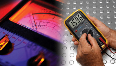
Voltmeters are used to measure voltage;ammetersare used to measure current; ohmmeters are used to measure resistance; and watt meters are used to measure power. It is important to understand that these meters provide a numerical value either in analog or digital format for the unit under test. Compare these meters to anoscilloscopethat is a piece of test equipment that provides a graphical picture of the waveform under test.
Traditionally, the analog meter had either a double-pivoted moving-coil type meter movement also known as a d’Arsonval meter movement, or a suspension-type moving-coil meter movement also known as a taut band suspension meter movement. The d’Arsonval meter movement was more common and was characterized by a coil of turns of wire wound on a rectangular frame suspended on jeweled bearings between the curved north- and south-pole pieces of a horseshoe-type permanent magnet. When direct current was passed through the coil, a magnetic field was created that reacted with the magnetic field of the horseshoe-type permanent magnet. The corresponding arc through which the coil rotated was proportional to the strength of the current. A pointer was attached to the moving coil and its deflection over a calibrated scale indicated a numerical value. Analog meters were commonly called VOMs (volt-ohm-millimeters). Prior to solid state electronics, analog meters were called VTVMs (vacuum tube volt-meters).

Figure 1. DC voltmeter circuit
The digital meter commonly called a DMM (digital multimeter) or DVM (digital voltmeter) usually had three parts: an input section for scaling either the voltage, current, or resistance, an integrator section to perform the A/D (analog to digital) conversion, and a counter section to display the pulse count of the measured quantity. Early DMMs had light emitting diode (LED) displays which required more current to operate but were easier to read in low-light environments. Modern DMMs used liquid crystal displays (LCD) as the display. The main advantage a DMM had over solid-state analog meters was high input resistance. Vacuum tube versions of the analog meters also had high input resistance.
Voltmeters
The voltmeter is a test instrument used to measure ac or dc voltage. The standard circuit shown in figure 1 is a multiplier resistor (Rm) in series with a DC milliammeter having an internal resistance (Ri). Using Ohm’s law, we can calculate what value of resistance (Rm) would need to be used to cause full-scale deflection of the meter at a designated voltage. To measure ac voltage, either half-wave or full-wave rectifiers would be used to convert the ac waveform into a dc value. Then the standard circuit would be used. The voltmeter is connected in parallel with the device under test.
Ammeters

Figure 2. DC ammeter circuit
The ammeter is a test instrument used to measure ac or dc current. The standard circuit shown in figure 2 is a shunt resistor (Rs) in parallel with a dc milliammeter having an internal resistance (Ri). Using Ohm’s law, we can calculate what value of resistance (Rs) would need to be used to cause full-scale deflection of the meter at a designated current. To measure ac current, either half-wave or full-wave rectifiers would be used to convert the ac waveform into a dc value. Then the standard circuit would be used. The ammeter is connected in series with the device under test. Clamp-on-type ac ammeters rely on the principle of magnetism about the conductor to measure current.
Ohmmeters
The ohmmeter is a test instrument used to measure dc resistance. There are two types of ohmmeters: the series type and the shunt type. In the series type, the resistance to be measured is connected in series with the meter movement. In the shunt type, the resistance to be measured is connected in parallel with the meter movement. The standard circuit shown in figure 3 consists of a dc voltage source, a dc milliammeter with internal resistance (Ri), and a variable resistor (Rv). An unknown resistance (Rx) is connected between the terminals which causes deflection of the meter indicating an ohmic value.

Figure 3. Series ohmmeter circuit
Wattmeters
The wattmeter is a test instrument used to measure ac or dc power. DC power is expressed as P = VI. DC power is the product of voltage times current. AC power is expressed as P = VI cos θ. AC power is the product of voltage times current times the cosine of theta. In effect, we could measure the current through a device and the voltage across a device and then multiply those numbers together to get dc power, provided that the internal resistance of the ammeter was low and internal resistance of the voltmeter was high relative to the device under test. We cannot do this in the ac case, because we are not taking into account the power factor. The standard circuit for a wattmeter shown in figure 4 consists of a voltage coil and a current coil which are compensated to account for power factor. It is important to note that a wattmeter measures true power not apparent power in an ac circuit.
Oscilloscope

Figure 4. Wattmeter circuit
The oscilloscope is a specialized test instrument that is used to measure voltage. It is comprised of the following: input amplifier sections, sweep oscillator, and synchronizing circuits. The oscilloscope allows you to troubleshoot a circuit by looking at the actual waveform being analyzed. It will not only give you a graphical representation of the waveform, but you will also be able to determine the amplitude, time, frequency, and phase relationships when comparing two waveforms on a dual-trace oscilloscope.
Circuit theory and network theorems allow you to calculate values of voltage, current, resistance, and power. Test instruments are practical tools that allow you to evaluate circuit parameters and compare measured values to calculated values.