In fact, I have written on this subject in this very publication, at least two such articles, in the past few years. Nevertheless, I routinely receive e-mails and phone calls with the questions about differences between bonding, grounding and neutral conductors, about differences in use of these conductors under the Rules of the Canadian Electrical Code and about differences in the Code requirements for sizing such conductors. So, let’s provide a bit of clarification again.
1. Bonding conductor
Bonding and bonding conductor are defined in the CE Code as follows:
“Bonding — a low impedance path obtained by permanently joining all non-current-carrying metal parts to ensure electrical continuity and having the capacity to conduct safely any current likely to be imposed on it.
Bonding conductor — a conductor that connects the non-current-carrying parts of electrical equipment, raceways, or enclosures to the service equipment or system grounding conductor.”
Based on these definitions, it is abundantly clear that bonding is a low-impedance path that is deliberately created between all non-current-carrying metal parts of electrical equipment in order to safely conduct any undesirable current (leakage or fault current) that could be inadvertently imposed on these metal parts during use of electrical equipment.
Bonding conductor is such conductor that actually connects these (normally non-current-carrying) metal parts of the electrical equipment (including cable armour and sheath, and metal raceways) with service equipment or with system grounding conductor. Let’s hold for a time being the explanation regarding connection of bonding conductor with the service equipment or with system grounding conductor, and let’s concentrate on a selection of size for a bonding conductor.
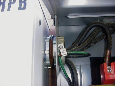
Photo 1. Does marking of this bonding conductor comply with the CE Code?
Bonding conductor is not considered to be a circuit conductor, as circuit conductors carry the circuit current under a normal operating condition, and ampacity of circuit conductors is selected in accordance with Rule 8-104 (or with other applicable rules of the Code depending on a type of connected loads such as motor, capacitor or heating loads). However, as a bonding conductor is intended to carry only a fault current, it must be sized so, as to have sufficient ampacity to carry the maximum fault current that could be accidentlyimposed on the non-current-carrying metal parts of a specific electrical equipment (of a specific connected load).
Selection of a bonding conductor size is governed by Rule 10-814(1).
This Rule states the following:
“10-814(1) The size of a bonding conductor shall be not less than that given in Table 16, but in no case does it need to be larger than the largest ungrounded conductor in the circuit.”
Table 16 offers the code users a criteria for selection of a bonding conductor size based on the ampacity of the largest ungrounded conductor in the circuit.
Appendix B Note on this Rule further clarifies this requirement by explaining that raceways permitted by the Code to be used as bonding conductors are deemed to be of adequate size to carry the fault current. This Appendix B Note also explains to the Code users that a bonding conductor provided as an integral component of a cable designed and constructed in accordance with an applicable safety standard (with one of the CSA Part II standards listed in Appendix A of the Code) is also deemed to be of adequate size for the purpose of Rule 10-814(1) to carry the maximum fault current that could be imposed on the non-current-carrying metal parts of electrical equipment connected by that particular cable.
Appendix B Note on Rule 10-814(1) “When a raceway or cable sheath enclosing the circuit conductors is permitted to be used as a bonding conductor for the equipment being supplied, it is deemed to be of adequate size for the purposes of this Rule. The bonding conductor incorporated into a cable assembly is sized in accordance with the relevant Part II Standard. Typically, the bonding conductor size in manufactured cables corresponds to the requirements of this Rule, but in some cases it may differ by one size, usually on the larger side. In any case, the bonding conductor incorporated into a cable assembly is deemed to be of adequate size for the purposes of this Rule.”
So, for example, if three 3/0 AWG copper conductors are selected from a 75 Deg. C column of Table 2 with ampacity of 200 A, and these conductors are installed in a PVC for a connection to,let’s say, a motor, then a copper bonding conductorsized at not less than 6 AWG must be selected from Table 16 based on ampacity ofsuch circuit conductors. If these three circuit conductors are installed in a rigid metal conduit, and this rigid metal conduit is used as a bonding conductor in accordance with Rule 10-618 of the CE Code, then the rigid metal conduit selected as per Table6 of the Code is deemed to be of adequate size to carry the maximumfault current that could be imposed on the metal enclosure of the motor connected to the circuit by these three 3/0 AWG copper conductors.
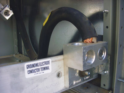
Photo 2. What should be the color of insulated grounding conductor?
Now is a good time to re-visit the Code definition of bonding conductor “Bonding conductor — a conductor that connects the non-current-carrying parts of electrical equipment, raceways, or enclosures to the service equipment or system grounding conductor,” and review the portion of this definition that describes connection of the bonding conductor to the service equipment or to the system grounding conductor.
Let’s start with connection of a bonding conductor to a grounding conductor. Before we’ll analyze the objective of this portion of definition, we need to clearly understand the meaning of a grounding conductor and grounding electrode.
2. Grounding conductor
The CE Code defines grounding conductor and grounding electrode as follows:
“Grounding conductor — the conductor used to connect the service equipment or system to the grounding electrode.
Grounding electrode — a buried metal water-piping system or metal object or device buried in, or driven into, the ground to which a grounding conductor is electrically and mechanically connected.”
Based on these two definitions, it should be clear that agrounding conductor at service equipment is such aconductor that connects aservice equipment enclosure to the grounding electrode and, via a grounding electrode, toground (toearth). This means that a service equipment enclosure (to which all other non-current-carrying metal parts of electrical equipment are connected by a bonding conductor) is reliably connected to ground (earth) by means of a grounding conductor and grounding electrode. Italso means that through this connection to ground/earth, all bonded non-current-carrying metal parts of electrical equipment are not only connected together (i.e., they are not only kept at the same potential), but they are actually bonded to ground (i.e., they are reliably kept at the potential of ground). It means that the purpose of a grounding conductor between the service enclosure and a grounding electrode is to always keep the equipotential plane established by the equipment bonding — at the potential of ground.
What about a system grounding conductor? In a typical solidly grounded system usually derived by a secondary of a utility or a customer-owned transformer or by a generator, a neutral point of the system is connected to ground via a system grounding conductor and a grounding electrode. This neutral point is also permitted to be connected to the enclosure of a transformer or a generator.
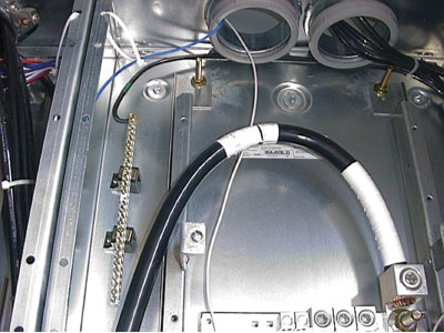
Photo 3. Does identification of the neutral conductor meet the CE
Code requirements?
So, how should a grounding conductor be sized? The answer to this question depends on the answer to another question: doesa grounding conductor carry a fault current?
Let’s review this question. When a fault current is imposed on a non-current-carrying metal part of electrical equipment which is bonded by a bonding conductor, this fault current is brought back to the service equipment by the bonding conductor sized in accordance with Table 16. What will be the effective path of a fault current back to the electrical power supply source in order to facilitate operation of the overcurrent protective device? Will this path be provided by a grounded service conductor which connects the bonded enclosure of the service equipment with the grounded neutral point of the source (with the grounded neutral point of the transformer or generator), or will it be provided by a grounding conductor and earth back to the neutral point of the source?
Of course, the effective ground fault current path will be provided only via a grounded service conductor and, for the purpose of facilitating operation of the overcurrent protective device, the fault current will never reach the source via a grounding conductor. This means that a grounding conductor does not carry a fault current for the purpose of facilitating operation of the overcurrent protective device. Of course, it does not. This is the reason that Table 17 has been removed from the CE Code, and Rule 10-812 states the following requirement for a grounding conductor sizing:
10-812 Grounding conductor size for alternating-current systems and for service equipment (see Appendix B) “The size of the grounding conductor connected to a grounding electrode conforming to Rule 10-700 shall be not smaller than No. 6 AWG.”
Appendix B note on Rule 10-812 offers the following clarification of this requirement:
“Appendix B Note on Rule 10-812 “It is intended that the size of a grounding conductor for a solidly grounded alternating-current system connected to a grounding electrode need not be larger than No. 6 AWG. The majority of fault current will be taken by the service grounded conductor of the system back to the source, and a grounding conductor sized not less than No. 6 AWG would be sufficient to carry any portion of the fault current that will flow through it.”
Let’s now elaborate on a “grounded service conductor” which will carry the fault current back to the source from the bonded service equipment. Usually such grounded service conductor is a neutral conductor.
3. Neutral conductor
Neutral is defined in the CE Code as follows: “Neutral — the conductor (when one exists) of a polyphase circuit or single-phase, 3-wire circuit that is intended to have a voltage such that the voltage differences between it and each of the other conductors are approximately equal in magnitude and are equally spaced in phase (see Appendix B).”
Appendix B provides the following clarification on this definition:
“Neutral — By definition, a neutral conductor of a circuit requires at least three conductors in that circuit. However, in the trade, the term “neutral conductor” is commonly applied to the conductor of a 2-wire circuit that is connected to a conductor grounded at the supply end. Care should therefore be taken in the use of this term when applying the Code.”
Neutral is acircuit conductor. However, neutral is identified (i.e., grounded) circuit conductor. Ina 3-phase, 4-wire circuit, or in a single-phase, 3-wire circuit, neutral conductor carries only unbalanced current. In a typical 2-wire circuit, neutral (identified) conductor carriesa full load current.
In fact, Subrules (3) and (4) of Rule 4-004 of the CE Code help the Code users in understanding the function of a neutral conductor in a circuit as follows:
“Rule 4-004(3) A neutral conductor that carries only the unbalanced current from other conductors, as in the case of normally balanced circuits of three or more conductors, shall not be counted in determining ampacities as provided for in Subrules (1) and (2).
Rule 4-004(4) When a load is connected between a single-phase conductor and the neutral, or between each of two phase conductors and the neutral, of a three-phase, 4-wire system, the common conductor carries a current comparable to that in the phase conductors and shall be counted in determining the ampacities as provided for in Subrules (1) and (2).”
Rule 4-022 provides guidance to the Code users regarding the minimum allowable size selection of a neutral conductor:
“Rule 4-024 Size of neutral conductor(1) The neutral conductor shall have sufficient ampacity to carry the unbalanced load. (2) The maximum unbalanced load shall be the maximum connected load between the neutral and any one ungrounded conductor as determined by Section 8 but subject to the following: (a) there shall be no reduction in the size of the neutral for that portion of the load that consists of (i) electric-discharge lighting; or (ii) non-linear loads supplied from a 3-phase, 4-wire system; and (b) except as required otherwise by Item (a), a demand factor of 70% shall be permitted to be applied to that portion of the unbalanced load in excess of 200 A. (3) The size of a service neutral shall be not smaller than the size of a neutral selected in accordance with Subrule (1) and shall (a) be not smaller than No. 10 AWG copper or No. 8 AWG aluminum; and (b) be sized not smaller than a grounded conductor as required by Rule 10-204(2), except in service entrance cable or where the service conductors are No. 10 AWG copper or No. 8 AWG aluminum. (4) In determining the ampacity of an uninsulated neutral conductor run in a raceway, it shall be considered to be insulated with insulation having a temperature rating not higher than that of the adjacent circuit conductors.”
But which Code requirement recognizes neutral conductor as a bonding conductor when the neutral conductor is installed betweentheneutral point of a solidly grounded system at the power supply sourceand the grounded enclosure of the service equipment?
The answer could be found in Rule 10-204(2) of the CE Code. Rule 10-204(2) “Where the system is grounded at any point, the grounded conductor shall: (a) be run to each individual service; (b) have a minimum size as specified for bonding conductors in Table 16; (c) also comply with Rule 4-024 where it serves as the neutral”;
This Code rule clearly recognizes the fact that the grounded conductor installed between the source of a solidly grounded supply system and the service is actually a bonding conductor, as it will carry the fault current between the bonded service enclosureand the source [see paragraph (b) above]. This rule also states that in addition to being a bonding conductor (and being sized as per Table 16) this grounded service conductor must be sized as per Rule 4-024 when it serves as a neutral conductor. Rule 10-624(4) specifically recognizes the fact that a grounded service conductor (regardless whether it is used as a neutral or just as a bonding conductor between the source of the solidly grounded supply and the service equipment) is permitted to bond the service equipment, thus re-enforcing its purpose by the Code of carrying the fault current between the service equipment and the source. Rule 10-624(4) states:
“The grounded service conductor on the supply side of the service disconnecting means shall be permitted to be connected to the metal meter mounting devices and service equipment, and where the grounded service conductor passes through the meter mounting device it shall be bonded to the meter mounting device.”
Hopefully, this exercise of reviewing functions of bonding, grounding and neutral conductors and criteria for selecting appropriate sizes of these unique conductors will help to further clarify the subject of bonding and grounding. However, as usual, in each case of design and installation, the respective AHJ should be consulted in discussing specific issues related to this subject.