Neutral point connection method
First, let’s define the different medium voltage earthing systems and then compare the advantages and disadvantages of each one. Earthing systems in medium voltage can be differentiated according to the neutral point connection method.
The various earthing systems in medium voltage systems are different in the way they operate and each has its advantages and disadvantages, which we shall now consider.
- Directly earthed neutral (Direct earthing)
- Unearthed neutral
- Resistance earthing
- Reactance earthing
- Petersen coil earthing
-
Directly earthed neutral
Also called Direct earthing
Description: An electrical connection is made be-tween the neutral point and earth.
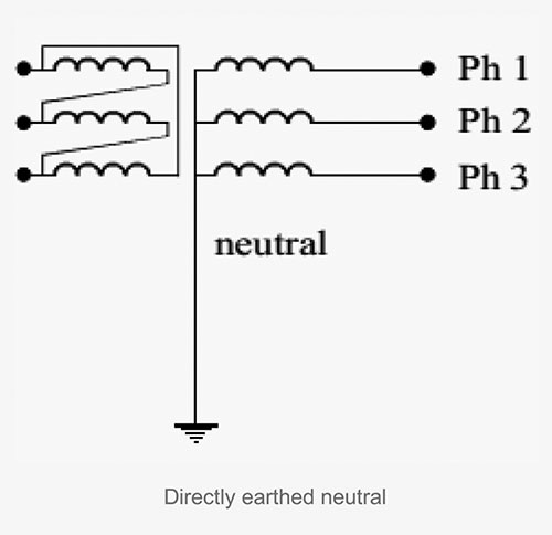
Operating technique: Compulsory switching on occurrence of the first insulation fault.
Advantages:
- Reduces the risk of overvoltages occurring.
- Authorizes the use of equipment with a normal phase to earth insulating level.
Disadvantages:
- Compulsory tripping upon occurrence of the first fault.
- Very high fault currents leading to maximum damage and disturbance (creation of induced currents in telecommunication networks and auxiliary circuits).
- The risk for personnel is high while the fault lasts; the touch voltages which develop being high.
- Requires the use of differential protection devices so that the fault clearance time is not long. These systems are costly.
-
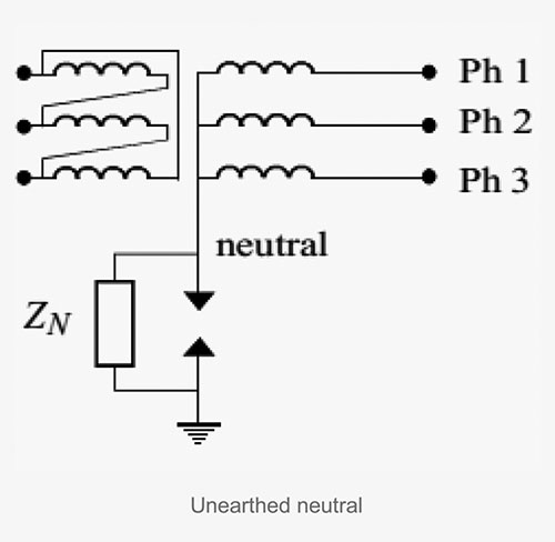
Unearthed neutral
Description: There is no electrical connection between the neutral point and earth, except for measuring or protective devices. A high impedance is inserted between the neutral point and earth.
Operating technique:
- No switching on occurrence of the first insulation fault — it is thus compulsory :
- To carry out permanent insulation monitoring; To indicate the first insulation fault;
- To locate and clear the first insulation fault;
- To switch upon occurrence of the second insulation fault (double fault).
Advantages:
- Provides continuity of service by only tripping upon occurrence of the second fault, subject to the network capacity not leading to a high earth fault current that would be dangerous for personnel and loads on occurrence of the first fault.
Disadvantages:
The unearthed neutral involves:
- The use of equipment whose phase-to-earth insulation level is at least equal to that of the phase-to-phase level. Indeed, when a permanent phase-earth fault occurs, the voltage of both unaffected phases in relation to earth takes on the value of the phase-to-phase voltage if tripping is not triggered on occurrence of the first fault. Cables, rotating machines, transformers and loads must therefore be chosen with this in mind;
- The risk of high internal overvoltages making it advisable to reinforce the equipment insulation;
- The compulsory insulation monitoring, with visual and audible indication of the first fault if tripping is not triggered until the second fault occurs;
- The presence of maintenance personnel to monitor and locate the first fault during use;
- Some difficulties implementing selective protection devices upon occurrence of the first fault; The risk of ferro-resonance.
-
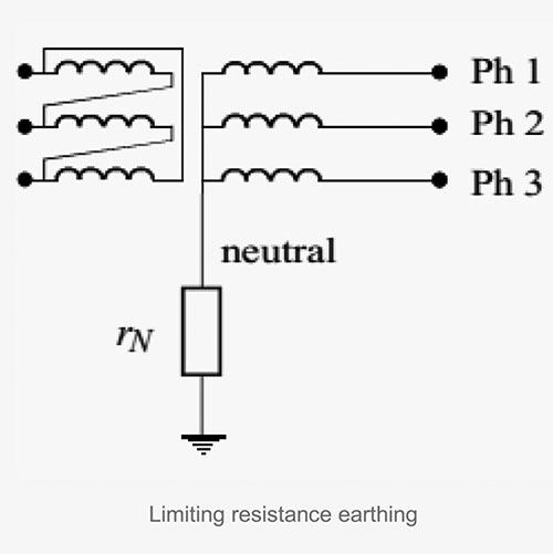
Resistance earthing
Limiting resistance earthing
A resistor is inserted between the neutral point and earth.
Operating technique: Switching upon occurrence of the first fault.
Advantages:
- Limits fault currents (reduced damage and disturbance).
- Dampens overvoltages of internal origin in that the limiting current
- Il is twice as high as the capacitive current IC giving Il > 2 IC.
- Does not require the use of equipment, and in particular cables, having a special phase/earth insulation level.
- Allows the use of simple selective protection devices.
Disadvantages: Tripping on the first fault.
-
Reactance earthing
Limiting reactance earthing
Description: A reactor is inserted between the neutral point and earth.
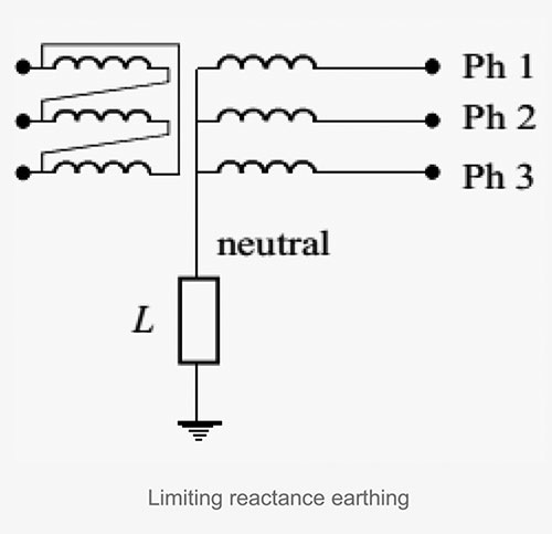
Operating technique: Switching upon occurrence of the first insulation fault.
Advantages:
- Limits the fault currents (reduced damage and disturbance).
- Allows the implementation of simple selective protection devices if IL >> IC.
- The coil, being of low resistance, does not have to dissipate a high heat load.
Disadvantages:
- May cause high overvoltages during earth fault clearance.
- Compulsory tripping upon occurrence of the first fault.
-
Petersen coil earthing
Description: A reactor L tuned to the network capacities is inserted between the neutral point and earth so that if an earth fault occurs, the fault current is zero.
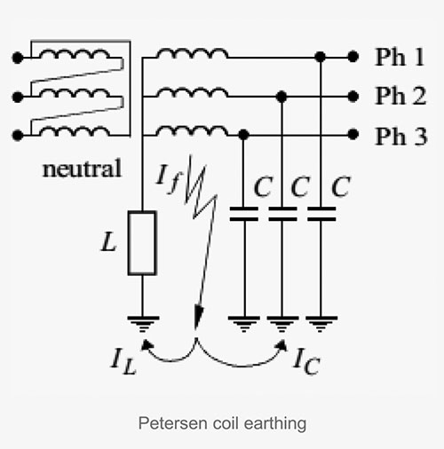
If = IL + IC
Where:
If – fault current
IL – current in the neutral earthing reactor
IC – current in the phase-earth capacitances
Operating technique: No switching upon occurrence of the first fault.
Advantages:
- If the reactance is such that 3 L0 C0 ω0 = 1 is re- spected, the phase-earth fault current is zero:
- Spontaneous clearance of non-permanent earth faults;
- The installation continues to operate in spite of there being a permanent fault, with tripping necessarily occurring on the second fault;
- The first fault is indicated by the detection of the current flowing through the coil. The coil is dimensioned so that permanent operation is possible.
Disadvantages:
- Difficulties establishing the condition 3 L0 C0 ω2 = 1 due to uncertain knowledge of the network’s capacity: the result is that throughout the duration of the fault, a residual current circulates in the fault. Care must be taken to make sure this current is not dangerous for personnel and equipment.
- The risk of overvoltages occurring is high.
- Requires the presence of monitoring personnel.
- Impossible to provide selective protection upon occurrence of the first fault if the coil has been tuned to: 3 L0 C0 ω2 = 1
- If it is systematically out of tune (3 L0 C0 ω2 ≠ 1) selective protection upon occurrence of the first fault is complex and costly.
- Risk of ferro-resonance.
Resource
Protection of Electrical Networks, by Christophe Prévé