For all protective conductors, including main and supplementary bonding conductors, electricians must perform a continuity test using a low-reading ohmmeter. For main equipotential bonding, there is no single fixed value of resistance above which the conductor would be deemed unsuitable. [See European terminology list at end of article]
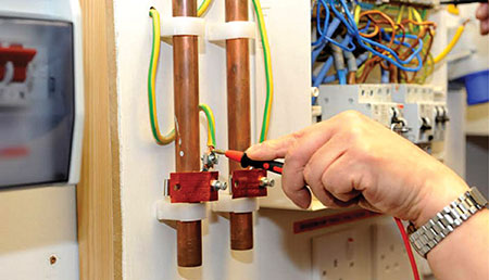
[Introduction photograph. Continuity of protective conductors (Photo credit: tradeskills4u.co.uk)]
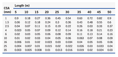
Each measured value, if indeed it is measurable for very short lengths, should be compared with the relevant value for a particular conductor length and size. Such values are shown in Table 1.
Where a supplementary protective bonding conductor has been installed between simultaneously accessible exposed and extraneous conductive parts the resistance of the conductor R must be equal to or less than 50/ Ia.
So, R ≤ 50/Ia, where 50 is the voltage, above which exposed metalwork should not rise and Ia is the minimum current, causing operation of the circuit protective device within 5s. For example, suppose a 45 A BS 3036 fuse protects a cooker circuit, the disconnection time for the circuit cannot be met, and so a supplementary bonding conductor has been installed between the cooker case and the adjacent metal sink.
The resistance R of that conductor should not be greater than 50/ Ia, which in this case is 145 A (IEE Regulations). So:
50/145 = 0.34 Ω
How then do we conduct a test to establish continuity of main or supplementary bonding conductors?
Quite simple really, just connect the leads from the continuity tester to the ends of the bonding conductor (figure 1). One end should be disconnected from its bonding clamp; otherwise, any measurement may include the resistance of parallel paths of other earthed metalwork.
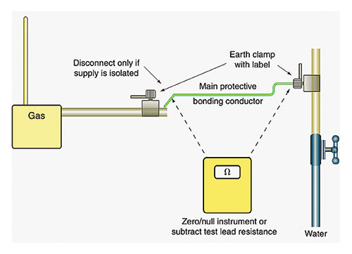
Remember to zero the instrument first or, if this facility is not available, record the resistance of the test leads so that this value can be subtracted from the test reading.
Important Note:
If the installation is in operation, never disconnect main bonding conductors unless the supply can be isolated. Without isolation, persons and livestock are at risk of electric shock.
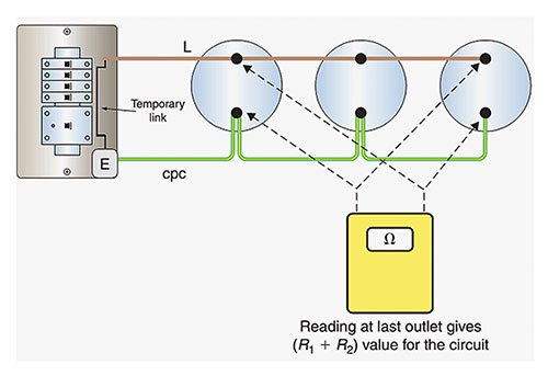
The continuity of circuit protective conductors (CPCs) may be established in the same way, but a second method is preferable, as the results of this second test indicate the value of (R1+R2) for the circuit in question.
The test is conducted in the following way (Figure 2):
- Temporarily link together the line conductor and CPC of the circuit concerned in the distribution board or consumer unit.
- Test between line and CPC at each outlet in the circuit. A reading indicates continuity.
- Record the test result obtained at the furthest point in the circuit. This value is (R1+R2) for the circuit.
There may be some difficulty in determining the (R1+R2) values of circuits in installations that comprise steel conduit and trunking and/or steel wire armoured (SWA) cables and mineral-insulated metal-sheathed (MIMS) cables because of the parallel earth paths that are likely to exist.
In these cases, continuity tests may have to be carried out at the installation stage before accessories are connected or terminations made off as well as after completion.
Terminology in Europe:
Supplementary bonding. Green and yellow conductors that connect accessible metal parts of electrical equipment (such as a heated towel rail) to accessible metal parts of items of electrical equipment and/or accessible metal parts of items that are not electrical (such as pipes). These connections are made to prevent a dangerous voltage between two accessible metal parts, in case there is a fault. You may need supplementary bonding for rooms containing a bath or shower, except where all circuits in the room are RCD protected and the main bonding is up to the required standard.
Residual current devices (RCDs). A sensitive switching device that trips a circuit when it finds an earth fault.
The circuit protective conductor(increasingly called the ‘c.p.c.’) is a system of conductors joining together all exposed conductive parts and connecting them to the main earthing terminal. Strictly speaking, the term includes the earthing conductor as well as the equipotential bonding conductors.
Reference
Electric Wiring: Domestic – Brian Scaddan IEng, MIET