
As an electrician who has turned to the dark side and become a building inspector, I sometimes ask myself why I became an inspector. Was it for the money? No. Was it for the glory & fame? Yeah, right. Was it my parents’ wish? Not likely as I was supposed to be a doctor. For me, I was in a place in my career where I felt I had seen everything, performed all aspects of electrical construction and it was time to take that rocking chair job called “electrical inspector.” Haha, the joke was on me, for as I soon found out, the role of electrical inspector is anything, but unexciting. And, I was wrong again when I figured out pretty quickly that I definitely hadn’t seen everything! As an inspector, I’m constantly surprised at what gets missed or forgotten. And with these large-scale PV projects, if even a few things get missed it can be overwhelming for the project leaders, especially when an issue has been duplicated across large swaths of the project, and they’re dealing with tight deadlines for project completion. One issue repeated a thousand times can be hard to correct, for instance, if it’s a material/product issue or an incorrect installation technique.
During the course of construction (which is usually organized chaos) on these large-scale PV projects, multiple activities will be occurring simultaneously, such as, but not limited to:
- electrical inspections
- structural inspections
- special inspections
- third-party inspections
- commissioning of
- 1000 and/or 1500 volt DC systems
- medium voltage equipment/cables
- switches and/or breakers at various voltages
- utility equipment
- general construction to complete
- grading activities
- substation steel erection
- concrete work
- drilling piers
- driving piles
- welding
- installing overhead and/or underground cables (miles of cable)
- material deliveries
It’s not unusual to have over 700 electricians at these sites in addition to laborers, ironworkers, linemen and support staff. And with all of these personnel performing construction work, some things do get missed during installation. This can lead to electrical equipment failures if issues are not discovered during inspections, or are later found during re-inspection. This can result in additional shutdowns for the deficiency, or worse yet, an unscheduled event that damages equipment beyond repair. Additionally, materials may arrive and/or get installed that are out of compliance with the required codes and/or project specifications and approved drawings. This will cause a project team to think outside the box and get creative to ensure the materials meet the job specifications and/or appropriate ASTM standards.
This article will attempt to identify the most common deficiencies encountered at these large scale projects and provide methods of verification you may find useful to achieve minimum code compliance.
Electrical Failures
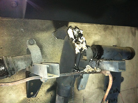
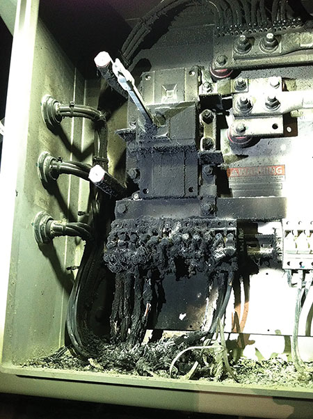
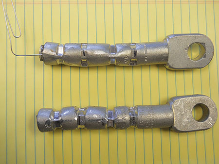
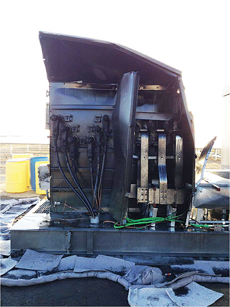
A loose electrical termination within any electrical circuit is bad. However, when dealing with 1000 or more volts, the terminations are critical. And, when an event occurs at these voltages, you’re usually going to be replacing the equipment (see photo 2 A & B). Spot checking at these sites is not recommended. At one recent project, a review of the terminations revealed a big issue (see photo 3). As you can see in this photo, this combiner had cables that were not terminated. That’s kind of a big deal. I stopped the inspection, quarantined the area, provided a written correction and notified the construction QC. After a sit down meeting with upper management, QC reported finding 6 more combiners with the same deficiency. I then requested to perform inspections at night where I could go back and check everything that had been reviewed during the day. That’s when this combiner (see photo 4) was found to be experiencing an event during the day which was obviously due to a barbecued terminal block. During our night inspections, my team of inspectors found several other combiners experiencing events that required replacements and several hundred more terminations that were only hand tightened. The lesson here is to be present during terminations installation to ensure they are correctly tensioned.
Another common occurrence is incorrect wiring at the combiner, where the electrician creates a bipolar circuit in the DC combiner at 2000 volts and develops a smoke show (see photo 5). This is not the kind of show any electrician wants. Normally this is discovered during Voc testing; however, if the electrician is unfamiliar with the test equipment and does not identify the polarity correctly, this will lead to a thermal runaway, which can destroy the equipment and may cause serious injuries to personnel in the vicinity. So a good lesson here is to ensure qualified personnel receive additional training on the deployment and operation of test equipment.
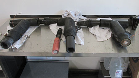
When inspecting medium/high voltage equipment terminations, it’s advisable to perform a component layout before installation. Inform the contractor you wish to review the specifications with the components and tools used in the fabrication of the cable termination. If there’s an issue with the materials, it’s better to catch this in the office than in the field after everything is high-pressed (see photo 6). Incorrectly installed medium voltage terminations can be extremely dangerous and usually lead to violent unscheduled events. And hopefully, you had a qualified NRTL evaluate these unlisted/uncertified BOL-T connectors and verify the installation; there will be hundreds, depending on the size of your project. The thing to remember here is to pay special attention to job specifications, require third party review, and monitor the installation.
Sometimes equipment, such as the medium voltage transformers, will arrive with deficiencies such as:
- leaking oil
- tap changers that function improperly
- bus supports missing
- issues discovered during testing at very low frequency (VLF)
- low side has insufficient number of available terminations for parallel conductors
- unlisted/certified equipment
This is just a partial list of what commonly occurs, and you will need to decide which course of action is appropriate for each deficiency. If, for example, the tap changer is misaligned (this has happened to me on several occasions) and operates incorrectly, the contractor will need to either pull the transformer for remediation at the manufacturer’s location or attempt to remediate at the site location. In either case, the original listing/certifying NRTL should be involved to witness the remediation to assist in identifying any other deficiencies and/or modification to the equipment. Designs do change and any modifications to the equipment would require a recertification and/or field evaluation to properly document the change. At one recent project, two 35 kV transformers experienced catastrophic events that led to further root cause analysis (RCA). The RCA identified a clearance issue inside the tank between the low-voltage lead and a high-voltage bushing; there was also an engineered relay setting that allowed the event to continue (see photo 7). Lesson learned here is to ensure the contractor is commissioning the equipment properly, soaking transformers, implementing VLF/ELF testing, and verifying windings resistance testing. And if you’re not comfortable with reviewing the results, you may require third party review of the data. Additionally, because this was a workmanship issue during the manufacturing process of the equipment, the original listing/certification NRTL must be involved to ensure the deficiency was properly corrected at the manufacturer’s location and that other units in the field can be identified and corrected.
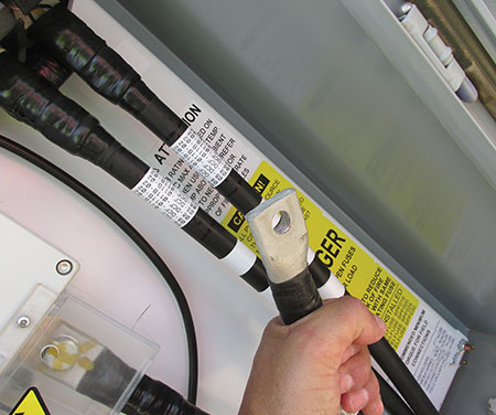
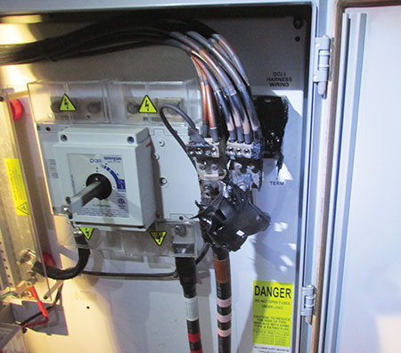
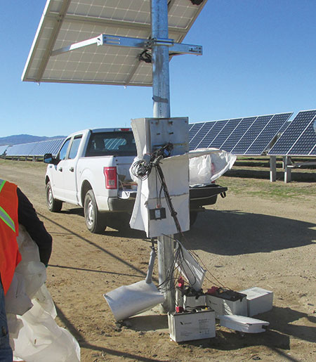
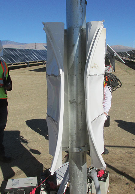
Another challenge is determining which equipment will require third-party electrical field evaluation. As stated in previous articles, most of the medium/high voltage equipment will not be NRTL-certified. Maybe you have a local ordinance that requires all electrical equipment to be NRTL-certified. That makes it easy; however, we have all been in a situation where maybe, based on the location and voltage, it’s really not necessary. Be careful here (see photo 8A & B). This unlisted/uncertified security camera system operated at 24 volts DC and produced an impressive event. Luckily, no injuries occurred. The lesson here is to require qualified NRTL evaluation to mitigate any risk to your client.
With all of the aforementioned occurring at your site, the building official criticizing methods of inspection, the phone ringing uncontrollably and emails piling up, you still have many other activities that require your attention. So let’s switch gears and look at ways to prevent issues in order to avoid project roadblocks. We’ll review the most common issues that occur relating to the International Building Code (IBC).
IBC REQUIREMENTS
As electrical inspectors, we tend to think of electrical compliance in terms of listing and certification, which basically covers ¼ of the installation; however, if you also deal with combination type inspections, then you’re dealing with structural materials that are possibly manufactured overseas (foreign) and you must use additional codes and standards to assist the contractor in gaining compliance to US Standards.
If you’re like me, I try to be extremely proactive in assisting the contractor in identifying roadblocks and possible speed bumps that may occur based on their methods and materials that may fall outside of the IBC requirements. If you’re unfamiliar with the requirements, and/or you don’t give the contractor a heads up in this area, the project can quickly turn into a freight train of non-compliance causing the customer to experience project delays, additional fees, and possibly material replacements (resulting in additional costs). Some will say it’s the contractor’s responsibility to know the minimum requirements and how to successfully navigate the system. And I agree partially. But over the years there has been a movement in which building departments, and state agencies are laying out the requirements and the methods to achieve compliance. This is ultimately a positive move; however, the concern is that policies change and codes are revised. So to dictate a means and methods in one state/jurisdiction is possibly setting up a contractor to fail if a code or policy is not recognized or is not code-compliant in the next state/jurisdiction that the contractor works in. So be careful if you’re recommending a system design for a contractor or dictating a construction method based on personal preference. The codes are not intended to be a design manual for unqualified personnel. Building departments need to be cautious in providing too much direction to contractors; it is the project leaders who must make the design decisions for their project. We can only tell them what is or is not code-compliant. Additionally, AHJs should be reticent in bending the rules or releasing contractors from following certain code requirements. It is ultimately the AHJ who is responsible for ensuring that the project meets all quality and safety standards. These days, I think we’ve all seen where jurisdictions or state agencies either do not hold a contractor to certain requirements that are politically unpalatable, or mandate an expedited permit process with no plan-check and only require one inspection because the contractor was unable to meet the minimum requirements of the AHJ. Whatever happened to good old fashioned studying the code books and designing a system that meets or exceeds the standards for quality and safety?
Every AHJ wants to assist the contractor in identifying issues before they develop and cascade into a disaster. And with these large-scale PV projects, it can get messy in a hurry and is usually a result of inexperienced engineers with insufficient hands-on electrical experience and contractors not reading the Code.
Steel Testing
As stated in 1705.2.1 and 1705.2.2 (IBC), special inspection for structural steel is required. Additionally, IBC Chapter 2203.1 states, “Identification of structural steel members shall comply with the requirements contained in the AISC 360 (American Institute of Steel Construction) …steel that is not readily identifiable as to grade from marking and test records shall be tested to determine conformity to such standards.”
What normally occurs is that the materials either arrive with no certified mill documentation and/or markings are absent. Or the materials arrived months earlier (no certified mill doc.) with no identifying markings for grade, heat number, and/or lot numbers traceable to the place of origin. This is called unidentifiable steel that requires testing to the appropriate ASTM Standard. As an example, structural tubing will most likely be required to meet ASTM A500 for cold-formed steel, or ASTM A501 for hot formed, with varying grades based on strength requirements. Refer to Chapter A in the AISC to identify the appropriate ASTM required for the following structural materials:
- Hot–rolled structural shapes
- Structural tubing
- Pipe
- Plates
- Bars
- Sheets
If you’re unfamiliar with steel testing, enlist the assistance of your structural department and develop a test procedure. Have a qualified test lab perform the testing per the ASTM. See below for some things to consider in your plan:
- Scope and purpose (identify the project and conformance to what standard)
- Sampling procedure
- Sample population shall consist of what? Are they all the same?
- Sequentially number the samples
- How many in each population?
* How many will be sampled out of each population
* How will they be selected- Check dimensions as follows
* Measure outside diameter shall not vary +/-0.75% and how many locations?
* Measure wall thickness shall not vary +/- 10%
* Record all measurements - Cut a sample from each selected material and how long? Are thermal means of cutting allowed? (normally not)
- Place samples into shipping create and label
* Lot #
* Quantity of pieces
* Unit numbers that were created by the inspector - Repeat until all individual samples have been collected
- Shipping information for the containers
- Record release of container
- Report distribution (sampling, lab results)
- Check dimensions as follows
- Testing procedure (developed by the EOR and reviewed and approved by the AHJ)
As you can see this is similar to an electrical field evaluation sampling plan, where destructive testing may be occurring to verify compliance to a standard.
High-Strength Bolts
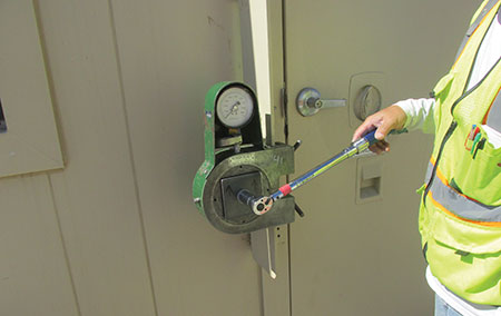
If high-strength bolts arrive without proper certified mill documentation and/or markings are absent, the testing and sampling discussed earlier also applies. Remember, Chapter 2204.2 of the IBC refers the reader to Chapter 17, which refers you to the AISC, Chapter A for the material identification and Chapter N (N5.6-1, -2, -3) for the inspection tasks required (see photo 9). Additionally, if the engineer of record (EOR) is specifying an aircraft fastener (or other alternative) in place of an A325, then additional testing is required such as the following:
- Chemical Analysis performed by Optical Emission
- Rotational Capacity
- Elastic Proof Load (externally threaded fastener)
- Wedge Tensile
- Hardness Testing – (Rockwell)
- Nut Proof Load (internally threaded fastener)
Chapter A3.3 of the AISC can assist with identifying the appropriate ASTM Standard and the test criteria required.
High-Strength Concrete
The next most common error is high-strength concrete electrical vaults that arrive with no documentation of special inspection. Or you arrive (because you’re not there on a daily basis) and it’s already installed. Normally these vaults are massive, comprised of 7000 psi concrete and consisting of several hundred vaults. Chapter 17 Table 17.5.3 would require special inspection of the reinforcing steel and concrete placement. But what do I do if it’s complete? Unfortunately, I have had this situation occur on two projects. After you have determined that the soils inspections were completed for excavation and re-compaction, the remaining two items of concern are the reinforcing steel and the compressive strength of the concrete. The method we used was ground penetrating radar (GPR) to verify the steel reinforcement to the shop drawings, and core samples were obtained for break testing. Again, if you’re unfamiliar with this type of remediation, it’s important to enlist the assistance of your structural group and document all the procedures and the terms/conditions before implementing the inspection. Some things to consider are:
- how many vaults will be inspected (I use 10%, and a failure doubles the sample group)
- how many core samples required (normally 3 samples from each vault opposite walls)
- will you accept certified mill documents provided post installed (GPR is excellent at determining rebar size), and
- will you require the EOR to sign off on the deviation?
With this information and the assistance of your structural team, you can determine compliance to the codes and standards.
Deeply Driven Piles
Another common occurrence is deeply driven piles or what Table 1705.7 calls Driven Deep Foundation Elements. Typically one or more of the following occurs:
- Pile refusal
o results in cutting off the excessive length with no documentation
- Wrong size pile is installed (too small)
- The top of the pile has excessive damage caused by installation
o top of pile is cut off, and new piece is splice welded on with no documentation
- Pile is installed in incorrect location and discovered by inspection team
This is just a sampling of what frequently occurs. However, all of these situations can be successfully remediated, and if the contractor discusses the project with the inspector first, then the inspector can assist with approved remediations for each case. It seems that lately the contractors are submitting approved remediations for many of the deviations detailed on the drawings. However, you will run into a few who don’t want to spend the extra time and money to think ahead. The first thing to remember is this: any deviation for structural components below grade requires two wet stamp approvals – one from the structural EOR and the second from the soils engineer. Again, they will need to develop a procedure for testing the piles if you’re dealing with components in the soil; but if you’re dealing with welding, then only the structural EOR needs to review the remediation procedure and get your buy in. I will only address the most common issue, which is pile refusal whereby the contractor has not achieved the minimum pile embedment. Chapter 18 of the IBC will need to be referenced by the EOR and ASTM D3689. The two sections are:
- 3.3.1.5 Uplift capacity of a single deep foundation element
- 3.3.2 Allowable lateral load
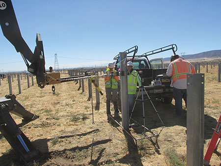
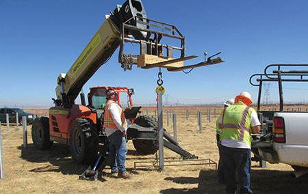
With this information, the engineers can develop a test procedure acceptable to the AHJ and begin the testing (see photos 10A & B). The procedure should also contain a remediation plan for any failures encountered in the field to keep the project progressing.
Soils
The last ‘gotcha’ item that occurs (a lot) is lack of special inspection for re-compaction of electrical trenches. Special inspection is required during the re-compaction. Typically, the electrical contractor only reviews the electrical drawings, and maybe the structural drawings, and may overlook the Geotechnical Investigation Report for the site. Chapter 18 of the IBC Section 1803 requires an investigation of the site that may include in-situ testing, laboratory testing, or engineering calculations all conducted by a registered design professional. Section 1804.5 provides information regarding shallow foundations adjacent to compacted fill (electrical trenches). And typically, the engineer will use the exception, which also directs the reader to Section 1705.6 for the special inspection requirements for the compacted fill and verification of in-place dry density of not less than 90%.
Unfortunately, what usually occurs is an inspection is requested for an electrical trench which is ¼ mile of medium voltage cable. After the trench is approved, the contractor starts filling in the trench, and I look around and say “where is the special inspector (SI)?” I inform them of the requirement only to return the next day, finding that everything is covered (without special inspection) and no reports. Now you have a choice – make them remove everything and start over with special inspection or involve the assistance of the geo-engineer and allow them to pot hole the trench at a specified distance and depth and generate a report acceptable to the AHJ. Use caution here if you’re dealing with MW of generation. Because of the lack of inspection for the backfilled material, any little void around the cable is a potential hot-spot, which could be a failure waiting to happen. In this situation, I always ask for written confirmation from the electrical EOR that he or she is ok with the method of verification/inspection, and sometimes my concerns are affirmed when the EOR makes the call to ‘dig it up and do it right.’ The cost of hiring a SI to oversee the re-compaction of electrical trenching is pennies compared to cost of repairing a medium voltage cable and lost revenue that goes along with the event.
SUMMARY
I did not touch on welding, shop drawings and/or wind-tunnel testing in this article; however, all will need to be formally submitted, reviewed and approved by your special inspectors and structural department. Here are some of the most common issues:
- Prequalified welding procedures do not follow the D1.1 Section 3
- Shop drawings were not cross-checked to the approved design drawings
- Wind-tunnel calculations are insufficient (how were they derived) and do not follow ASCE-7-10
These are just a few additional items to review. And remember, it’s the contractor’s responsibility to know and properly apply the codes and standards. And if you provide general guidance to assist the installer in being code-compliant, hopefully, they heed the advice. There have been projects where although the AHJ went above and beyond in assisting the EOR by identifying issues that appeared to be leading to a veritable train wreck when those warnings went unheeded, the project ended up with major project delays, staff stressed out, and additional cost for last minute testing and third party evaluations. Be aware that this can result in project leaders petitioning for a more ‘cooperative’ inspector for their site. But as long as you can point to the code book to back up your requirements, it’s to the AHJ’s benefit to keep the same inspector involved in order to best ensure the safety of the installation. But the lesson I have learned is that “you can present someone with an opportunity, but you cannot force him or her to take advantage of it.” It’s kind of like that old adage, whereby “you can lead a horse to water, but you can’t make it drink.”
Hopefully, this article touched on some of the major items of concern and some of the most common mistakes that occur on these projects. Our whole purpose is to ensure that the installations that we inspect will operate safely and efficiently for decades with limited maintenance and/or unscheduled power events. You can best achieve this by ensuring that you have a well-organized combination inspection team with a team of well-seasoned SI to properly review, inspect and approve these challenging projects.
If this article has generated any additional questions and/or comments, please contact the author by phone 619-318-7310 or email at shinspections.inc@cox.net