With most of the United States now on the 2014 or 2017 National Electrical Code (NEC) several topics and enforcement questions are routinely being discussed. This article will address some of the most relevant issues facing enforcement and installers concerning PV systems.
Rapid Shutdown— Certification of Equipment
The 2014 edition of the NEC introduced the Rapid Shutdown requirement in section 690.12. Details related to the enforcement of the 2014 NEC provisions can be reviewed in Jan/Feb 2015 IAEI magazine. Recently, Underwriters Laboratories (UL) have pointed out in various communications that inverters listed to UL 1741 Standard for Inverters, Converters, and Controllers, may not have had their interactive ac output terminals evaluated for compliance with the requirement to reduce voltage to 30 volts in 10 seconds. Incidentally, the time delay now allowed for compliance is 30 seconds as a result of Tentative Interim Amendment (TIA) 14-10 for the 2014 and the text of 2017 NEC. Regardless of the time delay, UL is correct in their statement that the interactive output terminals of a PV inverter have rarely been evaluated for the presence of ac voltage after the utility disconnect is opened. Instead, the interactive ac output of a PV inverter is extensively tested to make sure it “ceases to export power” to an interconnected balanced load circuit.
As of the writing of this article, the author is unaware of any inverter that passes the UL interactive requirements in the UL 1741 standard and would not be below 30 volts after 30 seconds when the ac circuit is interrupted. This does not guarantee that a new inverter design could not be developed that might not meet the voltage and time requirements of 690.12. These UL communications also suggest that if an installer or authority having jurisdiction (AHJ) is unsure whether a product complies with the 690.12 voltage requirement, that a simple field test could be performed. All that is necessary is for a properly rated ac meter to be placed on the inverter interactive output circuit and the inverter ac disconnected from the utility source opened. The ac voltage can be measured as it decays. All inverters tested by this author were below 30 volts in under 2 seconds. Inverters with low voltage ride through (LVRT) capabilities may take a few more seconds to get below 30 volts if the inverter’s grid-support functions are turned on. In either case, it is extremely unlikely that a PV inverter will have ac output voltage past 10 seconds. In fact, the TIA changing the 2014 NEC to increase the 10 seconds to 30 seconds was specifically to address the special case of inverters operating with grid-support functions turned on.
This brings up a very important distinction between the 2014 and 2017 NEC in 690.12.
The 2014 NEC states in 690.12(5):
“Equipment that performs the rapid shutdown shall be listed and identified.”
The 2017 NEC states in 690.12(D):
“(D) Equipment. Equipment that performs the rapid shutdown functions, other than initiation devices such as listed disconnect switches, circuit breakers, or control switches, shall be listed for providing rapid shutdown protection.”
The 2014 NEC requires equipment being used to meet the 2014 NEC be listed and identified. The term “identified” is defined in Article 100 as “Recognizable as suitable for the specific purpose, function, use, environment, application, and so forth, where described in a particular Code requirement.” While some have misinterpreted the 2014 language to require equipment listed specifically for Rapid Shutdown, it is clear from the 2014 Report on Proposals and Report on Comments that Code-Making Panel 4 (CMP-4) wanted installers and enforcement to NOT require equipment listed for Rapid Shutdown for the 2014 shutdown requirements. However, it is equally clear that the language of the 2017 NEC insists that products used to perform the shutdown functions be specifically listed for Rapid Shutdown.
While there is a specific UL Certification Requirement Decision (CRD) that UL is using to evaluate rapid shutdown equipment, the rapid shutdown addendum to UL 1741 is being voted on by the UL Standards Technical Panel (STP) in the fall of 2016 and should be published in early 2017. There are several products that are now listed to the UL CRD, which is a standard, and by other certification bodies with similar requirements. However, products meeting the newly published rapid shutdown addendum will only begin becoming available in 2017. It is important that the AHJ NOT require that products performing rapid shutdown be listed for rapid shutdown until the 2017 is enforced in their jurisdictions. Of course, as rapid shutdown listed products become widely available over the next year, these products would be ideal for compliance with the 2014 NEC and are required for those on the 2017 edition. For more information on how to enforce the 690.12 in the 2014, remember to read the article in Jan/Feb 2015 IAEI magazine. Stay tuned for a detailed article on the 2017 version of 690.12.
Grounding Electrodes for PV Systems
One of the most misinterpreted sections of Article 690 in the 2014 NEC is 690.47(D) [690.47(B) in the 2017 NEC]. The title of the section is “Additional Auxiliary Electrodes for Array Grounding” which is part of the reason that this section has been misinterpreted so often. The most common misconception in the enforcement of this section is that it always requires an extra electrode for PV systems, regardless of whether the structure on which they are installed already has electrode. It is understandable that this misconception exists because the section could benefit from some clarifying language. The original proposal submitted to the 2008 NEC by this author and John Wiles was intended to address structures supporting PV systems that did not have an existing grounding electrode. Many ground-mounted PV systems have been installed far from the utility service to which they are connected with no local electrode at the PV array. This is a potentially hazardous situation should a voltage potential develop between the service and the PV array. A local electrode helps stabilize voltage relative to ground near the array. Connecting exposed metal at the PV array to the local electrode reduces the hazard. Additionally, the effects of lightning are reduced by providing a local path directly to ground at the array rather than having to follow the equipment grounding conductor, possibly hundreds of feet, back to the utility service equipment where the electrode for the service is installed.
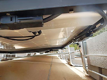
Typical ac cable system for ac modules
There remains confusion with the wording of 690.47(D). If a PV array is placed on a detached garage roof that has no electrode, that building would be required to install a grounding electrode according to 690.47(D). This electrode would be in addition to the electrode already installed at the service of the main house. This is an example of an additional electrode being required because the structure is separated from the structure where the utility service grounding electrode exists.
So what about buildings that already have a grounding electrode? Does 690.47(D) require an “additional” array electrode as is commonly required by AHJs? The short answer is that there was no intention for such an addition on the part of those that proposed this section to the NEC. It makes little sense from a technical point of view to add an additional electrode for array grounding if one already exists for the structure. In fact, it is likely that if an additional electrode is added to a house and a connection is made to that electrode directly from the PV array, without bonding the new electrode to the existing electrode, that this could create a problem during thunderstorms where nearby lightning strikes could induce differential voltages in the PV array and damage equipment.
The 2008 and 2014 NEC exceptions in 690.47(D) were intended to make additional electrodes unnecessary on buildings that already had electrodes. The exceptions are not as clearly worded as they could be, so many AHJs do not understand what these exceptions mean and simply disregard them. The first exception states that an additional electrode is not needed “where the load served by the array is integral with the array.” This could be interpreted to mean that it only applies to self-contained PV systems like pole-mounted PV lighting systems. A better interpretation of this exception is that, if the PV array is on the roof of the building it is serving, then the building already has an electrode and an additional electrode is unnecessary.
The second exception is equally confusing stating, “An additional array grounding electrode(s) shall not be required if located within 1.8 m (6 ft) of the premises wiring electrode.” One of several issues with this sentence is that the word “if” does not contain a clear object. One way to read the sentence is that if you were to drive a ground rod within 6 feet of an electrode, the electrode is unnecessary. That interpretation makes no sense because you cannot do both actions at the same time. We can better understand the intent of this exception by reading the 2008 NEC first draft version published on the NFPA website which reads:
“Where the grounding electrode would be adjacent to the main grounding electrode.”
That statement is clearer than the existing language. Basically this draft version says that this whole section is not necessary (1) if the structure already has an electrode, or (2) the PV structure is so close to the main structure that the main structure’s electrode is sufficient (less than 6 feet away as the existing words say).
Exception 2 is most consistently interpreted that if the PV array is more than 6 feet from premises electrode, that you need to add an electrode. This interpretation makes little sense since every roof-mounted PV system is at least 8 feet above the ground which would require every roof-mounted PV system to have an extra electrode. The more accurate way to read this exception is that if the structure on which the PV system is installed is within 6 feet of the building where the service is located (like an adjacent shade structure), or it is on the building where the service is located, then no additional electrode is necessary (as the first draft language more clearly states).
In summary, this provision only applies to PV arrays built on structures that do not already have a grounding electrode. This includes purpose-built structures for PV arrays and existing structures where PV is added but no previous electrode was installed. In the vast majority of roof-mounted PV systems where the building has an existing electrical service, this section does not apply.
The existing requirements for equipment grounding of the PV array in 690.43 covers all the necessary safety requirements. Only the old-style grounded micro-inverter PV systems need a grounding electrode conductor run to the PV array. All other types of PV arrays, including ac modules, dc optimizers, and PV source circuits, do not need a grounding electrode run to the PV array. Where 690.47(D) applies, the equipment grounding conductor in the PV array makes the electrical connection from the exposed metal to the local grounding electrode using a method in accordance with Part VII of Article 250.
The 2017 NEC clearly makes this point by completely rewriting all of 690.47 and clarifies the original intent of 690.47(D) in the 2014 and 2008 NEC.
Temporary Interim Amendments (TIAs) to the 2014 NEC
Four TIAs have recently been adopted that address important problems with the 2014 NEC as it relates to PV systems.
- Center-fed Panelboards in Dwellings
(TIA 14-12).
In the Western United States and other regions, center-fed service panels are commonplace. These are excellent load centers that spread out loads in the panel on either side of the main breaker. This reduces temperatures in the panel which is helpful in hot western climates. Enforcement concerns have arisen based on two very well written articles in the Jan/Feb 2013 IAEI magazine, entitled, “Unraveling The Mysterious 705.12(D) Load Side PV Connections” and reiterated in the July/August 2014 IAEI magazine article entitled, “Center-Fed Load Centers and Panelboards.” The issue raised by these articles was that the language of the NEC suggests that a center-fed panel cannot use the “120% rule” for compliance with 705.12(D)(7) in the 2011 NEC and 705.12(D)(2)(3) in the 2014.
The 120% rule simply stated allows inverter output circuits to be connected to panelboard busbars up to 120% of the ampere rating of the busbar if the connection is made at the opposite end of the bus from the utility supply breaker. This allowance originated from an exception for dwellings in 690.64(B)(2) in the 1987–2005 editions of the NEC. This exception simply allowed the sum of the main breaker plus the PV inverter breaker to add up to 120% of the busbar ampere rating. No stipulation was made in the exception for the location of the PV breaker with respect to the main breaker. When this exception was placed into positive language and extended to all PV installations in the 2008 NEC, the opposite end stipulation was added to help address PV on fully loaded commercial panelboards. This expansion of the 120% rule was applied equally to commercial and residential applications in an effort to keep the rule simpler.
TIA 14-12 addresses the special case of center-fed panels on dwellings so that those panels that have few, if any, continuously-loaded circuit breakers are allowed to apply the 120% rule. The only stipulation is that the PV breaker may be at either end of the busbar.
New 705.12(D)(2)(3)(e) in the 2014 NEC: “A connection at either end, but not both ends, of a center-fed panelboard in dwellings shall be permitted where the sum of 125 percent of the power source(s) output circuit current and the rating of the overcurrent device protecting the busbar does not exceed 120 percent of the current rating of the busbar.”
Generally, the PV system would be most effective if installed at the end of the more heavily loaded half of the panel as it will serve to spread the current density more evenly in that portion of the busbar. Commercial panelboards that may have center-fed configurations or multi-ampacity buswork can still install PV system circuit breakers under engineering supervision (705.12(D)(2)(3)(d) in the 2014 NEC and 705.12(D)(2)(3)(e) in the 2017 NEC.
- AC AFCI for Exposed Cables
deleted (TIA 14-11).
The 2014 introduced a requirement for AFCI protection of exposed ac cables connected to inverter output circuits of 240 Vac and 30 amps or less. Unfortunately, no AFCI equipment exists to meet this requirement that is capable of being backfed by inverter output circuits. There were assurances made to CMP-4 in the 2014 NEC cycle that such devices would be forthcoming quickly. Unfortunately, these products never materialized so CMP-4 removed this provision from the 2017 NEC. Since so many jurisdictions are just now enforcing the 2014 NEC, the case was made that there was an emergency nature related to removing this provision. This helps jurisdictions so they do not have go through the process of (1) understanding that these products don’t exist, and then (2) having to enforce 90.4, reverting to the previous code edition on this subject.
Another important reason for the TIA is to prevent the enforcement of an alternative interpretation of 705.12(D)(6). Since this provision as written addressed ac cable “that is not installed within an enclosed raceway,” some AHJs concluded that since ac AFCIs for this application did not exist, that all ac cable should be installed in raceways. Unfortunately, this interpretation neglects the fact that the exposed ac cable systems often used on micro-inverter PV systems, are not permitted to be installed in raceways because of the frequent cable branch attachments.
Enforcing a requirement for raceways for micro-inverter systems essentially outlaws the installation of all ac modules and micro-inverter PV systems. This was never the intent of 705.12(D)(6) so the only way to completely avoid these misinterpretations was process this TIA and remove the provision from the 2014 NEC.
- Rapid Shutdown Delay Extended from
10 to 30 seconds (TIA 14-10).
As discussed briefly in the Rapid Shutdown section of this article, the allowable delay for rapid shutdown equipment to meet the required 30-volt level was extended to 30 seconds. This aligns the 2014 NEC with the 2017 NEC time frame. The reason this required a TIA is that several large PV markets that are either on the 2014 NEC or getting ready to adopt the 2014 NEC (California) are beginning to adopt requirements for inverters to ride through long utility low-voltage conditions. The requirement to shut down for emergency responders could easily conflict with the utility requirement to continue to operate when there is low voltage on the utility system. Shutdown controls may have a difficult time distinguishing the difference between a utility problem and a firefighter operating a switch. The 30-seconds provides ample time to ride through the longest utility operating requirements and still be able to get to 30 volts in 30 seconds.
- Section 690.17 Type Exception Extended to All Subsections (TIA 14-9).
Part III of the 2014 edition of Article 690, Disconnecting Means, was heavily edited and reorganized for clarity. As part of that reorganization, the exception that related to connectors not having to meet the type requirements of 690.17 was moved to the end of section 690.17. However, the NEC style manual states that the exception must be located immediately following the clause it is modifying. Since 690.17 has several subsections in the 2014, a strict reading of the section would apply the exception only to 690.17(E) Interrupting Rating. It is nonsensical for the exception to only relate to that provision in the types of disconnects. The problem was resolved by simply clarifying that the exception applies to all 690.17 subsection. The new language refers to subsections (A) through (E) so that the style manual is properly followed and it is clear that the exception applies to all subsections.
Stay tuned for more articles related to the installation of PV systems. The now published 2017 includes many substantive revisions that clarify how to safely install PV systems. Future articles will discuss some of the most important changes in 2017 NEC related to PV systems.