The installation and inspection of an emergency electrical system are critical elements regarding the protection of persons set forth in Section 90-1 of the National Electrical Code. Requirements for the emergency electrical circuits and emergency system are more restrictive than the rules for normal circuits and systems in chapters 1 through 4 of the Code. It is important that those involved with the design, installation and inspection of the emergency system know and understand their responsibility in meeting the minimum requirements in the applicable codes. This article will take a closer look at a few of the key concepts and requirements that must be considered and verified regarding emergency electrical wiring and systems.
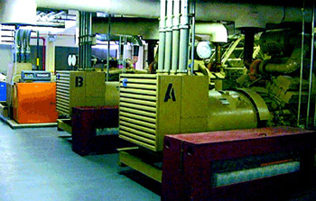
Large gen-sets for emergency systems
Model building codes are in place to serve as minimum regulations when constructing buildings or structures of any type of occupancy. Following these requirements of the applicable building code will result in a building or structure that is essentially free from hazards and safe from a building safety standpoint. Model building codes refer to the National Electrical Code for minimum requirements for electrical safety. The NEC is the most widely adopted code in the world, and is recognized by the model code groups and code enforcement agencies as the most comprehensive document containing electrical safety requirements for the protection of persons and property (see NEC 90-1).
The building code(s) include requirements for establishing emergency exits and egress paths out of a building or occupancy in emergency conditions. The building code enforcement agency, usually in cooperation with the fire department, establishes criteria when an emergency system is required in a building or occupancy. The characteristics and use of a building or structure, predicate when an emergency electrical system is required. NEC Section 700-16 requires that means of egress and exit signs be illuminated. In most occupancies, the emergency electrical system is intended to stand by until an emergency incident happens. The system’s design and purpose is to provide minimum electrical power for lighting and other essential loads to allow the safe evacuation of the building or structure. There are emergency systems that are designed to allow the safe evacuation of persons from a structure, but in some occupancies such as health care facilities, the life safety and essential electrical system work in harmony to evacuate the general public and assure continuity of power and lighting essential for life for those patients who are unable to evacuate the building. Article 517 includes the requirements for not only the life safety systems as specified in Article 700 but also goes further to require an essential electrical system for life safety and life support for patients. See Article 517 and NFPA 99 for more detailed information on this subject.
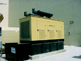
Generator exterior enclosure
Chapter seven of the NEC is titled Special Conditions. Emergency electrical systems fall into the category of special conditions. Three articles deal with standby power in cases where the normal power to a building is interrupted: Article 700, Emergency Systems; Article 701, Legally Required Standby Systems; and Article 702, Optional Standby Systems. This writing will focus on the emergency system requirements as specified in Article 700. The main differences between Article 700 and Articles 701 and 702 are that the requirements for emergency systems in Article 700 are essential for safety to human life and well-being.
Section 700-1 sets the stage for emergency systems. Emergency systems are those systems legally required and classed as emergency by municipal, state, federal, or other codes, or by any governmental agency having jurisdiction. These systems are intended to automatically supply illumination or power, or both, to designated areas and equipment in the event of failure of the normal supply or in the event of accident to elements of a system intended to supply, distribute, and control power and illumination essential for safety to human life. Here the Code indicates that if it is mandated by any state, federal, or local governmental agency that an emergency system is required, then a redundant emergency electrical power system that meets the minimum requirements of Article 700 must be installed in addition to the normal electrical power distribution system. Once it has been determined that an emergency system is required, the electrical design and engineering for the project must incorporate the emergency system into the design for that particular project. The provisions of Article 700 are in addition to or amendatory of the basic rules in chapters 1 through 4 of the Code. This means that except as modified by Article 700, the emergency electrical system must meet the minimum requirements as provided in the general rules of the NEC.

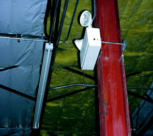
Unit equipment with cord- and plug-connection as per 700-12(e)
Emergency systems are generally installed in places of assembly where artificial illumination is required for safe exiting and for panic control in buildings subject to occupancy by large numbers of persons, such as hotels, theaters, sports arenas, health care facilities, and similar institutions. Emergency systems may also provide power for such functions as ventilation where essential to maintain life, fire detection and alarm systems, elevators, fire pumps, public safety communications systems, industrial processes where current interruption would produce serious life safety or health hazards, and similar functions.
Design of the System
There are a couple of real important concepts to consider when designing an emergency electrical system. First, is the power source. Section 700-12 lists the sources for an emergency system. Usually the building construction and the type of occupancy determine the required source of emergency power. It could be as simple as a battery backup light, referred to in the Code as “unit equipment,” or it could be a larger source such as an emergency electrical power generator (see photos 1, 2, and 3.) Second, location of this power source is critical. The design should include a consideration to locate the normal source or service to the building sufficiently remote from the emergency power source. The idea here is to locate the emergency source so that a failure, explosion, or fire at the normal source will not jeopardize the emergency source and cause it to fail also.
All equipment used for the emergency electrical system is required to be approved for emergency use. See the definition of “approved” in Article 100. Transfer equipment including automatic transfer switches used in emergency systems must be identified for the emergency system use. Emergency transfer switches are required to be electrically and automatically operated and mechanically held. Transfer switches used on emergency systems must supply only loads classified as emergency loads.
The Witness Test
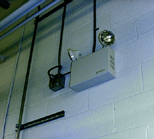
Unit equipment hand-connected to local area lighting circuit as per 700.12
Section 700-4(a) of the NEC requires that the authority having jurisdiction conduct an actual witness test of the emergency electrical system. This is a requirement related to performance that is mandated by the Code. This witness test is an actual dry run of the system to verify that it will function when there is an interruption of the normal power to the building or structure. This test is required to be performed with the emergency system fully loaded with the maximum anticipated load. This would indicate that if a fire pump were classified as one of the emergency loads and connected to the emergency system, it must be included when the witness test is performed. Testing is also required periodically thereafter. Many facilities install automatic exercisers on generator sets to exercise the combustion engine or prime mover periodically. This is not a substitute for the performance test of the emergency system itself. During the witness test, inspectors verify that there is a transfer to emergency power within ten seconds. This is required by Section 700-12. This witness test is also the time where verification that the capacity of the emergency electrical system is adequate and will carry the full anticipated load as required in Section 700-5. Another item verified during the witness testing is if there is enough illumination in the path of egress as mandated by the model building code. The building code requires a certain foot-candle power at the floor line in the egress path. Inspectors often carry foot-candle meters to verify that the level satisfies the minimum code requirements. These tests are often performed in the evening for a true perspective as to how the lighting will function in a worse case scenario. The object is simply to have enough light to exit the building. The Code does not give requirements for emergency lighting outside the building. [See photo 4 and 5]
Section 700-16 requires that the emergency lighting system be designed so that the failure of any individual lighting element, such as the burning out of a light bulb, must not leave the area that requires emergency lighting in total darkness. Where high intensity discharge lighting is installed, such as mercury vapor, high-pressure sodium, or metal halide lighting, the emergency lighting is required to operate until the normal lighting has been restored. There is a cooling down period required for the ballasts in these types of lighting fixtures. Interruption of normal power to the building, if only for a short period of time, could leave the area in darkness when these types of lighting fixtures are installed. A couple of designs are usually employed to handle this situation. These types of fixtures can be purchased with a small re-strike lamp installed. Another method is to install time-delay features in listed unit equipment devices. There are also fixtures available known as “hot strike” style fixtures. These are designed to re-strike immediately when normal power is restored. Whichever method is chosen for the design, it is important that the area not be left in darkness and that within ten seconds, lighting is provided, be it normal or emergency. This is verifiable during the witness test of the functionality and performance of the emergency lighting system.
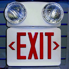
Self-contained unit equipment emergency lighting and exit sign combination
The inspection should also include a verification that if audible and visual signals have been installed, they are set to annunciate the following warning signals. They must indicate the battery is carrying a load, a battery charger is not functioning, and there is a ground fault that exists on the emergency system. This ground-fault indication is only required where ground-fault protection is installed on the emergency system. Section 700-26 indicates that ground-fault protection shall not be required for equipment with automatic disconnecting means. If it is provided, it is required to be located where practicable in accordance with the requirement of Section 700-7(d)[see photo 6].
Separation between Normal and Emergency Circuits
Section 700-9 covers the requirements for emergency system circuit wiring. The Code requires that circuits of the emergency system are to be kept entirely independent of the normal wiring circuits. This again is a minimum requirement to assure that the failure of normal circuits, such as a ground fault or short circuit, will not damage or disable the emergency circuits. There are four exceptions to this main rule where normal and emergency circuits are permitted to occupy the same enclosure. Continuity of service is essential for the emergency system.
Section 700-9(c) also goes on to require that emergency wiring circuits must be designed and located so as to minimize the hazards that might cause failure of these circuits. These failures might be caused by flooding, fire, icing, vandalism, or other adverse conditions (see figure 1).
Fire Protection or Feeders
Fire protection is required for emergency feeder circuits when emergency systems are installed in assembly occupancies greater than 1000 persons or in buildings with a height exceeding 75 feet (high rise buildings). Meeting the fire protection requirements for emergency system feeders starts in the engineering/designing/plan review stages of a project. The installation of the feeders in accordance with Section 700-9(d) is verified by field inspection and usually includes both the structural and electrical inspectors working together. Section 700-9(d) reads as follows:
(d) Fire Protection. Emergency systems shall meet the following additional requirements in assembly occupancies greater than 1000 persons or in buildings above 75 ft (23 m) in height with any of the following occupancy classes: assembly, educational, residential, detention and correctional, business, and mercantile.
1. Feeder-circuit wiring shall meet one of the following conditions:
a. Be installed within buildings that are fully protected by an approved automatic fire suppression system
b. Be a listed electrical circuit protective system with a minimum 1-hour fire rating
c. Be protected by a listed thermal barrier system for electrical system components
d. Be protected by a fire-rated assembly having a minimum fire rating of 1 hour
e. Be embedded in a minimum of 2 in. (50.8 mm) of concrete
f. Be a cable listed to maintain circuit integrity for a minimum of 1 hour when installed in accordance with the listing requirements
2. Equipment for feeder circuits (including transfer switches, transformers, panelboards, etc.) shall be located either in spaces fully protected by approved automatic fire suppression systems (sprinklers, carbon dioxide systems, etc.) or in spaces with a 1-hour fire resistance rating.
FPN: For the definition of occupancy class, see Section 4-1 of Life Safety Code, NFPA 101-1997.1
Emergency Sources
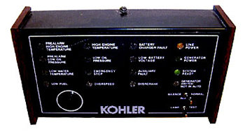
Typical signals as per 700-7
Five sources for emergency power are acceptable as prescribed in Section 700-12: storage batteries, generator sets, uninterruptible power supplies (UPS systems), separate services, and unit equipment. When selecting an emergency source of power, one should consider the occupancy and the type of service to be rendered, whether of minimum duration, as for evacuation of a theater, or longer duration, as for supplying emergency power and lighting due to an indefinite period of current failure from trouble either inside or outside the building.
Unit equipment is the term the Code uses to describe a battery pack unit that usually is self-contained and includes two lighting units which are able to be aimed into the egress path (see photos 5a and 6a). The Code describes unit equipment as follows:
(e) Unit Equipment. Individual unit equipment for emergency illumination shall consist of the following:
1. A rechargeable battery
2. A battery charging means
3. Provisions for one or more lamps mounted on the equipment, or shall be permitted to have terminals for remote lamps, or both, and
4. A relaying device arranged to energize the lamps automatically upon failure of the supply to the unit equipment.2
These units are required to be connected to the lighting circuit supplying the normal lighting for that area and connected ahead of any local switches in that lighting circuit. This is another function that is verified in the witness testing required by Section 700-4(a)[see photo 7]. The testing button on the unit equipment is not intended to take the place of a witness test. This button, although it is labeled “test” on the unit, is only intended to test the battery of the unit. It has nothing to do with a witness test. The branch circuit feeding the unit equipment is required to be identified in the panelboard from which the circuit originates. The Code requires, in Section 110-22, that all circuits be identified as to the load they serve. It is not uncommon to see a “lock-on” type device installed on the circuit breaker supplying unit equipment. This is done to minimize the chances of battery discharge. There is currently no requirement in the Code for this. Many designers will specify this feature on those circuits. Unit equipment is also available in larger styles, which are designed to supply several remote lighting units. When emergency illumination fixtures are not part of the unit equipment or installed remote they are required to be wired with one of the wiring methods specified in chapter 3 of the Code. It is not permissible to use a low voltage wiring method which may be allowed for a Class 2 or 3 circuit in Article 725. This means that a raceway or cable wiring method in accordance with chapter 3 is required for these circuits.
Summary
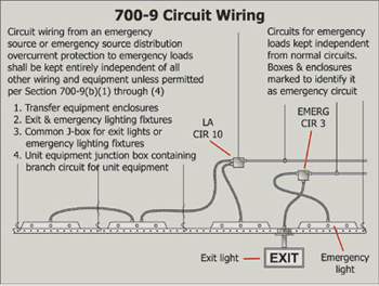
Emergency circuit separation
Installations and inspections of emergency systems are an important part of the integrity life safety systems where required in buildings or occupancies. The building codes and the National Electrical Code are used in harmony to provide the minimum requirements for the exit and egress paths. One of the most important inspections that should be made is the witness test of the emergency system required by Section 700-4(a). As Murphy’s Law says, if something can go wrong, it may very well go wrong, sooner if not later. When these emergencies happen, the emergency system must operate when called upon to do so. The NEC requires a witness test of the complete emergency system when installed. The authority having jurisdiction is required to conduct or witness this test. Compliance with the minimum requirements in Section 700-4 of the NEC is only the first step. Periodic testing and written record keeping of these tests are required by Section 700-4(d) and should be kept, and a schedule should be adhered to. These requirements are the minimum requirements set forth in the National Electrical Code. There may be local amendments in your specific area or region. Always check with the authority having jurisdiction responsible for these inspections in your area.
1 National Electrical Code, NFPA 70-1998 (Quincy, MA: National Fire Protection Association, 1998) Article Section 700-9(d), Fire Protection, p. 70-502-503.
2 National Electrical Code, NFPA 70-1998 (Quincy, MA: National Fire Protection Association, 1998) Article Section 700-12(e), Unit Equipment, p. 70-504.