When speaking of electromagnetic compatibility problems, the usual first thought goes in the direction of radio and television interference. But in the big field of electromagnetic compatibility, problems can also occur between different parts of an electrical distribution network. This article will report on a very unusual resonance phenomenon and a simple, practical solution. The reader might be advised that this case occurred in Europe, where other electrical codes apply, but this situation may also happen anytime in all installations with power factor correction capacitors within the U.S., even when all articles of the NEC have been properly observed.
The modern tendency of company fusions, sales and renewal of corporate identities is like a warm spring rain to the whole electric sign industry. Especially with big companies and chains spending hundreds of thousands of dollars for new neon signs on their corporate headquarters and subsidiaries every year. Most of these outdoor sign installations were well planned and installed code compliant by larger sign companies with well-trained people—and are not of the “high-noon” installation type.1
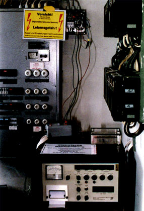
Photo 1. The failing back-side sign was fed from a panel on the twelfth floor, where large elevator motors, air-conditioning systems and other inductive loads were branched
It was to one of these big installations that I was called, about six months after the sign had been put up, because of repeated “sign failures.” As the site was on the back side of the headquarters building (facing the parking lot), the general managers noticed unlit parts every morning and complained to the sign company immediately—so it was a job of particular importance.
The documentation provided showed the dimensioning of the eleven transformers, each with 8000 V at 80 mA output, was perfectly matched to the tube load. Recalculating and a check of current and voltage in every secondary circuit with an oscilloscope did not disclose any unusual values.
A critical inspection revealed that the whole sign installation was perfectly to code. (In Germany, the EN 50107 standard, the equivalent to Article 600 of the NEC, applies for installations; transformers have to comply to EN 60150.)
The sign electrician reported to me that once in a while ground-fault protective devices on the transformers would trip randomly. (The EN 50107 standard requires for all neon sign and cold cathode installations to use secondary circuit ground-fault protection; it is mandatory for only certain neon signs in the U.S., according to UL 2161.) Also, the house technician on duty reported circuit breakers tripping randomly.
Tracing the feeding line (branch circuit), I found that the eleven transformers (each of 736 VA) totaling approximately 8 kVA were powered by two phases (each 230 volts to neutral in the 230/400 volts 3-phase connected WYE on two legs). The circuit breakers were two times 20 amps fast blow characteristics.
As EN 50107 permits a maximum load of only 3.2 kVA per branch circuit [similar to NEC 600-5(b)(2)], equivalent to a 16-amp breaker, the 20-amp breakers were illegal. The transformers were high power factor types with integrated phase shift capacitors, thus the line will “see” a total load of 3982 watts at cos phi > 0.95, so the breakers should not trip, except for the switching on surge current. What made me think, was noticing that the neutral conductor (larger than 14 AWG) got a little too warm to touch.
So I advised the sign electrician to rewire the feed (branch circuit) from the panel in larger size (similar to 12 AWG), split the transformer load to 3-phase circuits and best possible symmetry in WYE, as well as to use three 16-amp circuit breakers for the inductive loads, to comply with the branching load limit of the code.
After almost a year, I was called again; the managers were still complaining about the sign and the circuit breakers tripping randomly. But only the sign on the back side of the building was experiencing problems; an identical one on the front never failed. No one could tell me where the panel, circuit breaker or circuit for the front sign originated—no documentation was available.
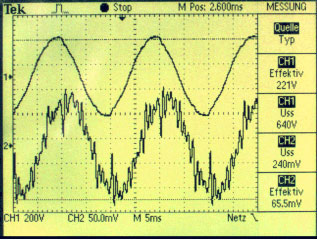
Photo 2. The voltage was almost sinusoidal, but the current waveform was dominated by harmonics
The failing back-side sign was fed from a panel on the twelfth floor, where large elevator motors, air-conditioning systems and other inductive loads were branched (see photo 1), thus transients and surges can be assumed. Using a powerline disturbance monitor (Programmed Power type 3402, modified for phase and direction indication), all three phases were monitored for a week to look for overvoltages and transients.
When installing the monitor, the branch-circuit voltages and currents were checked with an oscilloscope. As photo 2 shows, the voltage was almost sinusoidal, but the current waveform was dominated by harmonics— especially the neutral carried non-sinusoidal pulse waveform with a non-harmonic frequency of 161.8 Hz. As the inset shows, repetitive current surges of more than 17 amperes in the neutral could be observed (photo 3, inset).
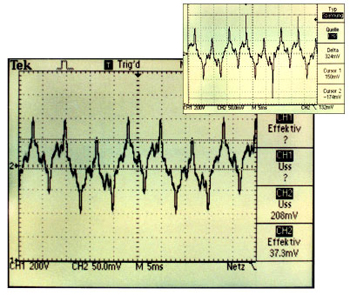
Photo 3. As the inset shows, repetitive current surges of more than 17 amperes in the neutral could be observed
The power monitor recorded within one week a total of 78 transients of more than 100 volts over 230 volts, where 44 surges occurred on one day within 2 minutes. None of the circuit breakers tripped during this time.
The in-house electrician mentioned that the building was supplied from the company’s own power station in the steel mill across the street, and that they could not find the panel from which the same neon sign on the front of the building was fed. He also could not tell me what the two old fuses marked “Neon” on the panel in photo 1 were powering (they were checked and found to be live).
Circuit Simulation
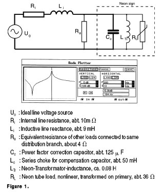
Figure 1. A computer simulation of the basic equivalent circuit was set up
One item that could cause the non-harmonic frequencies in the neutral pointed to a possible interaction of line and load, one of the uncommon problems of electromagnetic compatibility. A computer simulation of the basic equivalent circuit as shown in figure 1 was set up. The known parameters were the impedance of the neon transformer, the capacitance for correcting the power factor, and the measured resonant frequency. By varying the line equivalent characteristic and observing the Bode-Plot (or frequency response, inset in photo 3), the series resonance at 164 Hz occurred at an inductive line impedance of approximately 9 mH, whereas the power factor correction parallel resonance at 50 Hz was not affected.
The available literature listed different possible solutions to this type of reactive line feedback.
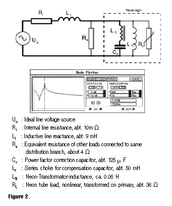
Figure 2. The older literature suggested in the case of series resonance problems of motors and power factor correction capacitors with inductive line impedances to wire series chokes in the line to the capacitor
The most expensive action is to reduce the short-circuit impedance of the resonant branch—which might require a new utility transformer, bigger size wiring to be run through the whole building and may cost more than $1 million.
Another common solution is the use of active filters to restore the sinusoidal current waveform. Active filters have been possible for a few years now that fast, high power IGBT transistors and fast FFT-based computer controllers have become available.
The older literature suggested in the case of series resonance problems of motors and power factor correction capacitors with inductive line impedances to wire series chokes in the line to the capacitor (see figure 2). This is, in many cases, a good solution where resonance occurs only at harmonic frequencies.
The simulation of the Bode-characteristics of a choked capacitor showed that the resonance intensity remains unchanged, only the frequency is shifted; but not only on the series resonant frequency, the parallel resonance for power factor correction is also affected.
In the present problem it could be observed that the resonant frequency of 161.8 Hz was not constant, but varied for 5 to 10 Hz randomly up or down, probably depending on other loads in this part of the distribution system being switched on and off.
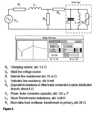
Figure 3. The simulation in figure 3 shows that the introduction of an ohmic resistor of 1 to 1.5 ohms in the line to the neon installation will bring down the resonance peak approximately 20 dB
So installing chokes in series with the capacitors would only have shifted the series resonant frequency and so the problem, but not solved it permanently, up to the point where the line impedance would again accidentally cause resonance.
The only solution could be to reduce the intensity of the series resonance. Reducing the resonance enhancement of a line-to-neutral or common circuit is achieved by introducing additional losses.
The simulation in figure 3 shows that the introduction of an ohmic resistor of 1 to 1.5 ohms in the line to the neon installation will bring down the resonance peak approximately 20 dB (equivalent to 1/100 power level). This resistor would create a loss of about 60 to 90 watts per phase and reduce the voltage at the primary terminals of the neon transformer approximately 2 to 4 percent, which will reduce the available reignition voltage on the secondary accordingly. A recalculation of the transformer loading showed that there is enough reserve, so no transformers needed to be changed or secondary circuits rewired.
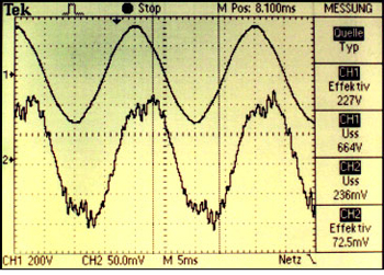
Photo 4. Demonstrates the reduced harmonic current content compared to photo 2
Considering the wire resistance from the panel with the old “neon” fuses to the front sign should present a resistance of about 1.3 ohms, which might be the reason that the front sign did not show resonance problems, as a possible resonance is damped enough by the wire resistance to prevent the fuse being blown.
Experimental proof
To prove whether the resonance damping calculated would also occur in the installation, three large (500 watts each), 1.5-ohm resistors were wired in the phase lines. Photo 4 demonstrates the reduced harmonic current content compared to photo 2, whereas photo 5 shows that the high peaks in the neutral are no longer existing, and the amplitude of the non-harmonic component has been remarkably reduced.
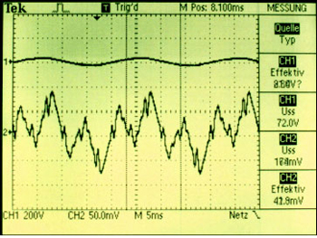
Photo 5. Shows that the high peaks in the neutral are no longer existing, and the amplitude of Photo 5. Shows that the high peaks in the neutral are no longer existing, and the amplitude of the non-harmonic component has been remarkably reducedthe non-harmonic component has been remarkably reduced
So to summarize, a classical problem of electromagnetic incompatibility of a distribution system and a load, both of which were installed to code, was caused by formation of a series resonant circuit of a line inductance in the distribution system and a power factor correction capacitance in the load, caused to resonate due to nonlinear characteristics in the line and load.
The resonance enhancement of the current caused the circuit breaker to trip when the resonant current was higher than the safe current for the wiring, which occurred randomly, depending on the load situation in the distribution system. A simple but effective cure was to dampen the series resonance by introduction of ohmic resistors.
1 In the sign business an improper installation is often called “high noon” when all parts have to be delivered on site up to high noon, so the mechanical installation will be finished at dusk (daylight view approval), then the electrical installation including night appearance approval (and cash collection) is done before midnight, and the whole crew will be on the run and out-of-state before dawn—and never seen again. Often also called “fly-by-night installs.”