One of our primary responsibilities in the electrical trade is to select electrical conductors, and one of the primary responsibilities of electrical inspectors is to judge those selection decisions properly. Recognizing the importance of this issue, the task group appointed to review Article 220 for the 2005 NEC decided to recommend adding a new Example 3A to Annex D covering this topic. It does not focus on load calculations but on conductor selection instead. Unlike most examples, the loads are stipulated,1 the context is industrial, and the distribution is 480Y/277V. The proposal has been endorsed by the NEC Technical Correlating Committee and accepted by CMP-2, subject to public comment as in the case of all proposals. This article uses the setup illustrated in the proposed example (see figure 1 for a visual reference) to present the concepts that need to be mastered. The example assumes 75°C conductor terminations and then calculates the overcurrent protection and conductor sizes required for two 3-phase 4-wire feeders run in a common raceway through a utility access passageway that includes process steam, resulting in a 35°C ambient.

Photo 1. A 20-amp circuit breaker marked as acceptable for 75°C termination
Middles and Ends of Wires Require Separate Calculations
The key to making correct conductor selection decisions is to remember that the end of a conductor is different from its middle. Special rules apply to calculating conductor sizes based on how the terminations are expected to function. Entirely different rules aim at assuring that conductors, over their length, do not overheat under prevailing loading and conditions of use. These two sets of rules have nothing to do with each other—they are based on entirely different thermodynamic considerations. Some of the calculations use, purely by coincidence, identical multiplying factors. Sometimes it is the termination requirements that produce the largest conductor, and sometimes it is the requirements to prevent conductor overheating. You cannot tell until you complete all the calculations and then make a comparison. Until you are accustomed to doing these calculations, do them on separate pieces of paper.
Current is always related to heat. Every conductor has some resistance, and as you increase the current, you increase the amount of heat, all other things being equal. In fact, the heat increases rapidly, by the square of the current. The ampacity tables in the NEC reflect heating in another way. As the excerpts from Table 310.16 show, the tables tell you how much current you can safely (meaning without overheating the insulation) and continuously draw through a conductor under the prevailing conditions—which is essentially the definition of ampacity in Article 100: “The current, in amperes, that a conductor can carry continuously under the conditions of use without exceeding its temperature rating.”

Table 1. Table 310.16
Ampacity tables show how conductors respond to heat. Ampacity tables (see the Table 310.16 excerpt, for example) do much more than what is described in the previous paragraph. They show, by implication, a current value at or below which a conductor will run at or below a certain temperature limit. Remember, conductor heating comes from current flowing through metal arranged in a specified geometry (generally, a long flexible cylinder of specified diameter and metallic content). In other words, for the purposes of thinking about how hot a conductor is going to be running, you can ignore the different insulation styles. As a learning tool, let’s make this into a “rule” and then see how the NEC makes use of it: A conductor, regardless of its insulation type, runs at or below the temperature limit indicated in an ampacity column when, after adjustment for the conditions of use, it is carrying equal or less current than the ampacity limit in that column.
For example, a 90°C THHN 10 AWG conductor has an ampacity of 40 amps. Our “rule” tells us that when 10 AWG copper conductors carry 40 amps under normal-use conditions, they will reach a worst-case steady-state temperature of 90°C just below the insulation. Meanwhile, the ampacity definition tells us that no matter how long this temperature continues, it will not damage the conductor. That is not true of the device, however. If a conductor on a wiring device gets too hot for too long, it could lead to loss of temper of the metal parts inside, cause instability of nonmetallic parts, and result in unreliable performance of overcurrent devices due to calibration shift.
Termination Restrictions Protect Devices
Because of the risk to devices from overheating, manufacturers set temperature limits for the conductors you put on their terminals. Consider that a metal-to-metal connection that is sound in the electrical sense probably conducts heat as efficiently as it conducts current. If you terminate a 90°C conductor on a circuit breaker, and the conductor reaches 90°C (almost the boiling point of water), the inside of that breaker will not be much below that temperature. Expecting that breaker to perform reliably with even a 75°C heat source bolted to it is expecting a lot.

Figure 1. The setup proposed for a new Example 3A for the 2005 NEC
Testing laboratories take into account the vulnerability of devices to overheating, and there have been listing restrictions for many, many years to prevent use of conductors that would cause device overheating. These restrictions now appear in NEC 110.14(C). Smaller devices (generally, 100 amp and lower, or with termination provisions for 1 AWG or smaller conductor) historically were not assumed to operate with conductors rated over 60°C such as Type TW. Higher rated equipment assumed 75°C conductors, but generally no higher for 600-volt equipment and below. This is still true today for the larger equipment. (Medium voltage equipment, over 600 volts, has larger internal spacings and the usual allowance is for 90°C per 110.40, but that equipment is beyond the scope of this article.) Today, smaller equipment increasingly has a “60/75°C” rating, which means it will function properly even where the conductors are sized based on the 75°C column (Table 310.16).
Photo 1 shows a “60/75°C” marking on a 20-amp circuit breaker, which means it can be used with 75°C conductors, or with 90°C conductors used under the 75°C ampacity column. Both the panelboard and the device at the other end of the conductor must make the same allowance for a 75°C temperature assumption to be acceptable. Otherwise the 60°C column applies. Always remember, though, that conductors have two ends. Successfully using the smaller (higher ampacity) conductors requires equivalent markings on the device at the other end. Refer to figure 2 for an example of this principle at work.
Splices are terminations. Not all terminations occur on electrical devices or utilization equipment. Some terminations occur in the middle of a run where one conductor is joined to another. The same issue arises when we make a field connection to a busbar that runs between equipment. Busbars, usually rectangular in cross section, are often used to substitute for conventional wire in applications involving very heavy current demands. When you make a connection to one of these busbars (as distinct from a busbar within a panel), or from one conductor to another, you only have to be concerned about the temperature rating of the compression connectors or other splicing means involved. Watch for a mark such as “AL9CU” on the lug. This one means you can use it on either aluminum or copper conductors, at up to 90°C, but only where the lug is “separately installed” (NEC text).
Lug temperature markings usually mean less than they appear to mean. Many contactors, panelboards, etc., have termination lugs marked to indicate a 90°C acceptance. Ignore those markings because the lugs are not “separately installed.” Apply the normal termination rules for this kind of equipment. What is happening here is that the equipment manufacturer is buying lugs from another manufacturer who does not want to run two production lines for the same product. The lug you field install on a busbar, and use safely at 90°C, also works when furnished by your contactor’s OEM. But on a contactor you do not want the lug running that hot. The lug will not be damaged at 90°C, but the equipment it is bolted to will not work properly.
Sizing Circuit Protection for Continuously Loaded Devices
The NEC defines a continuous load as one that continues for three hours or longer. Most residential loads are not continuous, but many commercial and industrial loads are. Consider, for example, the banks of fluorescent lighting in a store. Not many stores always stay open less than three hours at a time. Although continuous loading does not affect the ampacity of a conductor (defined, as we have seen, as a continuous current-carrying capacity), it has a major impact on electrical devices. Just as a device will be affected mechanically by a heat source bolted to it, it also is affected mechanically when current near its load rating passes through it continuously. To prevent unremitting thermal stress on a device from affecting its operating characteristics, the NEC restricts the connected load to not more than 80 percent of the circuit rating. The reciprocal of 80 percent is 125 percent, and you will see the restriction stated both ways. Restricting the continuous portion of a load to 80 percent of the device rating means the same thing as saying the device has to be rated 125 percent of the continuous portion of the load. If you have both continuous and noncontinuous load on the same circuit, take the continuous portion at 125 percent, and then add the noncontinuous portion. The result must not exceed the circuit rating.
Suppose, for example, a load consists of 51.6 amps of noncontinuous load and 67.8 amps of continuous load (119 amps total) as has been proposed for Example 3A (figure 1) and shown with only the essential elements in figure 3. We will use the figure 3 format throughout the rest of this article in order to avoid confusion as we gradually introduce the complicating factors that affect these calculations. Figure 1 combines all aspects of the calculation procedure and we will return to it at the end. For now, simply calculate the minimum capacity we need to allow for our connected equipment (not conductors) as follows:
Step 1: 51.6 A x 1.00 = 51.6 A
Step 2: 67.8 A x 1.25 = 84.8 A
Step 3: Minimum = 136.4 A
Section 220.2(B) allows minor fractions of an ampere to be discarded.2 A device such as a circuit breaker that will carry this load profile must be rated no less than 136 amps, even though only 119 amps actually pass through the device. In the case of overcurrent protective devices, the next higher standard size would be 150 amps. In general, for overcurrent protective devices not over 800 amps, the NEC allows you to round upward to the next higher standard overcurrent device size.

Figure 2. Always consider both ends of a conductor when making termination temperature evaluations
Two common mistakes. Having gone this far, it is easy to make two mistakes at this point. First, although you can round up in terms of the overcurrent device rating, you cannot round up in terms of conductor loading, not even one ampere. A 1 AWG conductor in the 75°C column can carry 130 amps. If your actual load runs at 131 amps, you have to use a larger conductor. Second, when continuous loads are a factor, you have to build in additional headroom on the conductor sizes to assure that the connected devices perform properly. This last point results in constant confusion because it may seem to contradict what we said about conductor ampacity tending to be the factor that determines minimum conductor size.

Figure 3. Overcurrent protective devices must be sized to accomodate the calculated load plus 25 percent of any portions of the load that are continuous.
We handle conductors, and we worry about conductors getting overheated. Device manufacturers do not worry about conductors in this sense; they worry about their devices getting overheated and not performing properly. Continuous loads pose real challenges in terms of heat dissipation from the inside of mechanical equipment. Remember that when you bolt a conductor to a device, the two become one in the mechanical as well as the electrical sense. Device manufacturers rely on those conductors as a heat sink, particularly under continuous loading. The NEC allows for this by requiring conductors carrying continuous loads to be oversized according to the same formula that applies to the device, namely an additional 25 percent of the continuous portion of the load.
Derating can affect conductor heating dramatically. The 10 AWG THHN conductor, for example, could carry 40 amps for a month at a time without damage to itself. But under those conditions the conductor would represent a continuous 90°C heat source. Now watch what happens when we (1) size the conductor for termination purposes at 125 percent of the continuous portion of the load, and (2) use the 75°C column for the analysis. This calculation assumes the termination is rated for 75°C instead of the default value of 60°C:
Step 1: 1.25 x 40 A = 50 A
Step 2: Table 310.16 at 75°C = 8 AWG
We go from a 10 AWG conductor to an 8 AWG conductor (6 AWG if the equipment does not have the allowance for 75°C terminations). Now that is just one customary conductor size, but look at it from the device manufacturer’s perspective. A 10 AWG carrying 40 amps continuously is a continuous 90°C heating load. What about the 8 AWG? Use the ampacity table in reverse, according to our “rule.” Forty amps happen to be the ampacity of an 8 AWG, 60°C conductor. Therefore, any 8 AWG conductor (THHN or otherwise) will not exceed 60°C when its load does not exceed 40 amps. By going up just one conductor size, the termination temperature dropped from 90°C to 60°C. The NEC allows manufacturers to count on this headroom.
To recap, if you have a 40-amp continuous load, the circuit breaker must be sized at least at 125 percent of this value, or 50 amps. In addition, the conductor must be sized to carry this same value of current based on the 75°C ampacity column (or 60°C if not evaluated for 75°C). The manufacturer and testing laboratory count on a relatively cool conductor to function as a heat sink for heat generated within the device under these continuous operating conditions.

Figure 4. These imaginary pull boxes at each end of the run illustrate how to separate raceways/cable heating calculations from termination calculations
In the feeder example (figure 1), including the 125 percent on the continuous portion of the load brings us to a 136-amp conductor, and the next larger one in the 75°C column is 1/0 AWG. Use the 75°C column here because the 150-amp device exceeds the 100-amp threshold (below which the rating is assumed to be 60°C). Remember, only 119 amps (67.8 amps + 51.6 amps) of current actually flow through these devices. The extra 17 amps (the difference between 119 amps and 136 amps) is phantom load. You only include it so your final conductor selection is certain to run cool enough to allow it to operate in accordance with the assumptions made in the various device product standards.
Devices rated for 100 percent continuous loading. There are devices manufactured and listed to carry 100 percent of their rating continuously, and the NEC recognizes their use by exception. Typically these applications involve very large circuit breaker frame sizes in the 600-amp range (although the trip units can be smaller). Additional restrictions accompany these products, such as on the number that can be used in a single enclosure and on the minimum temperature rating requirements for conductors connected to them. Learn how to install conventional devices first, and then apply these 100-percent-rated devices if you run across them, making sure to apply all installation restrictions covered in the directions that come with this equipment. The warning about conductors having two ends applies here with special urgency; be aware that one of these devices at one end of a circuit does not imply anything about the suitability of equipment at the other end.
The Middle of the Conductor—Preventing Conductors from Overheating

Figure 5. An example, using again the feeder with 51.6 amps of noncontinuous load and 67.8 amps of continuous load.
None of the preceding discussion has anything to do with preventing a conductor from overheating. That’s right. All we have done is to be sure the device works as the manufacturer and the test lab anticipate in terms of the terminations. Now we have to be sure the conductor does not overheat. Again, ampacity is by definition a continuous capability. The heating characteristics of a device at the end of the run do not have any bearing on what happens in the middle of a raceway or cable assembly.
To reiterate, you have to compartmentalize your thinking at this point. We just covered the end of the conductor; now we will get to the middle of the conductor. Remember being asked to do these on separate pieces of paper? Lock the first one up, and forget everything you just calculated. It has absolutely no bearing on what comes next. Only after you have made the next series of calculations should you retrieve the first sheet of paper. And only then should you go back and see which result represents the worst case, and therefore governs your conductor choice.
Imaginary pull boxes? If you have trouble making this distinction, and many do, apply an imaginary pull box at each end of the run (figure 4). This part of the article covers selecting conductors to run between the two pull boxes, and nothing more. The first part of the article covered selecting conductors of appropriate size to terminate on devices, and nothing more. The final step in the process is to compare the two results and choose conductors that satisfy both sets of requirements. At that point, and only at that point, you can turn off your mental image of those pull boxes because they no longer serve any purpose.
Review the ampacity definition. Conductor ampacity is its current-carrying capacity under the conditions of use. For NEC purposes, two field conditions affect ampacity, and they are mutual heating and ambient temperature. Either or both may apply to any electrical installation. Both of these factors reduce ampacities from the table numbers.

Figure 6. Elevated ambient temperatures also force ampacity derating on conductors
Mutual heating. A conductor under load dissipates its heat through its surface into the surrounding air; if something slows or prevents the rate of heat dissipation, the temperature of the conductor increases, possibly to the point of damage. The more current-carrying conductors there are in the same raceway or cable assembly, the lower the efficiency with which they can dissipate their heat. To cover this mutual heating effect, the NEC imposes derating penalties on table ampacity values. Penalties increase with the number of current-carrying conductors in a raceway or cable assembly. NEC Table 310.15(B)(2)(a) limits the permissible load by giving derating factors that apply to table ampacities. For example, if the number of conductors exceeds three but is fewer than seven, the ampacity is only 80 percent of the table value; if the number exceeds six but is fewer than eleven, 70 percent; more than ten but fewer than twenty-one, 50 percent, and so on. However, if the raceway is not over 24 in. long (classified as a nipple), the NEC assumes heat will escape from the ends of the raceway and the enclosed conductors need not have their ampacity derated [see 310.15(B)(2)(a) Exception No. 3].
Count only current-carrying conductors for derating calculations. Equipment grounding conductors are never counted for ampacity correction, but are for fill. Only one conductor in a pair of three-way switch travelers need be counted. A neutral conductor that carries only the unbalanced current of a circuit (such as the neutral conductor of a threewire, singlephase circuit, or of a fourwire, threephase circuit) is not counted for derating purposes in some cases. Grounded conductors, however, are not always neutrals. The grounded (“white”) conductor of a twowire circuit carries the same current as the hot conductor and therefore is not a neutral. If you install two such twowire circuits in a conduit, they must be counted as four conductors.

Figure 7. The two feeders in figure 5 as they would be affected by adding the elevated ambient temperature shown in figure 6
How (and when) to count neutrals. Although neutral conductors are counted for derating purposes only if they are actually current-carrying, it is increasingly common in commercial distribution systems derived from three-phase, four-wire, wye-connected transformers to find very heavily loaded neutrals. If the circuit supplies mostly electricdischarge lighting or other nonlinear loads you must always count the neutral. The neutrals in the proposed Example 3A are counted for the same reason. Remember also that any time you run just two of the three-phase conductors of a three-phase, four-wire system together with the system neutral, that neutral always carries approximately the same load as the ungrounded conductors and must be counted. This arrangement is very common on large apartment buildings where the feeder to each apartment consists of two-phase conductors along with a neutral, but the overall service is three-phase, four-wire.
However, the neutral of a true single-phase, three-wire system (e.g., 120/240-volt) need not be counted, because harmonic currents fully cancel in these systems. The overwhelming majority of single-family and small multifamily dwellings and most farms have these distributions, which greatly simplifies your conductor selection calculations.
Conductor ampacity derating. Now that you know how to count the number of current-carrying conductors in a conduit, it is time to learn how to apply NEC rules to the result. Using the NEC directly means going from the ampacity table to the derating factor (by which you multiply), and comparing the result to the load. That is great for the inspector who checks your work (the summary at the end of this article uses this process), but it does not help you pick the right conductor in the first place. You want to go the other way: Knowing the load, you want to select the proper conductor. Figure 5 shows an example, using again the feeder with 51.6 amps of noncontinuous load and 67.8 amps of continuous load. Suppose you have two of those feeders supplying identical load profiles and run in the same conduit. That would be eight current-carrying conductors in the raceway. For this part of the analysis, ignore continuous loading and termination problems. Remember, you should be using a fresh sheet of paper for this calculation.
Start with 119 amps of actual load (51.6 amps + 67.8 amps, rounded to three significant figures as specified in the proposed new Example 3A), and divide (you are going the other direction, so you use the opposite of multiplication) by 0.7 [see Table 310.15(B)(2)(a)], to get 170 amps in this case.2 In other words, any conductor with a table ampacity that equals or exceeds 170 amps will mathematically be guaranteed to carry the 119-amp actual load safely. A 1/0 AWG THHN conductor, with an ampacity of 170 amps, will carry this load safely under the conditions of use, and it might appear to work. Whether it represents your final choice depends on what comes from the analysis that follows, under the heading “Choosing a conductor.”
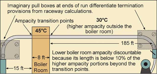
Figure 8. There is a limited exception to the weak-link-in-the-chain principle, illustrated in this drawing.
Ambient temperature problems. High ambient temperatures hinder the dissipation of conductor heat just as in the case of mutual heating. To prevent overheating, the NEC provides ambient temperature derating factors at the bottom of the ampacity tables. In our example, circuit conductors go through a 35°C ambient. Their ampacity goes down (for 90°C conductors) to 96 percent of the base number in the ampacity table, as shown in figure 6. Here again, we start with 119 amps, and divide by the 0.96 to get 124 amps. Any 90°C conductor with an ampacity equal to or higher than 124 amps would carry this load safely.
What happens if you have both a high ambient temperature and mutual heating, as shown in figure 7? Divide twice, once by each factor. In this case:
119 A ÷ 0.7 ÷ 0.96 = 177 A
A 2/0 AWG THHN conductor (ampacity = 195 amps) would carry this load without damaging itself. Again, this would be true whether or not the load was continuous, and whether or not the devices were allowed for use with 90°C terminations. Don’t cheat; the termination calculations are still supposed to be locked up in another drawer.
When diminished ampacity applies only to a small part of the run. You occasionally will run into installations where most of a circuit conforms to Table 310.16 but a small portion requires very significant derating. For example as illustrated in figure 8, your circuit may be 208 ft long, with 200 ft in normal environments and 7 ft of it passing through a corner of a boiler room with a very high ambient temperature. The NEC generally observes the weak-link-in-the-chain principle and requires the lowest ampacity anywhere over a run to be the allowed ampacity. However, for very short runs where the remainder of the circuit can function as a heat sink, the NEC allows the higher ampacity to be used.

Figure 9. Never lose site of the fact that at the end of the day, the overcurrent protective device must protect its conductors.
Specifically, anytime ampacity changes over a run, determine all points of transition. On one side of each point the ampacity will be higher than on the other side. Now measure the length of the conductor having the higher ampacity (in this example, the portions not in the boiler room) and the length having the lower ampacity (in this example, in the boiler room). Compare the two lengths. NEC 310.15(A)(2) Exception allows you to use the higher ampacity value beyond the transition point for a length equal to 10 ft or 10 percent of the circuit length having the higher ampacity, whichever is less.
In this case (200-ft run beyond the 8 ft in the boiler room), 10 percent of the circuit length having the higher ampacity would be 20 ft, but you cannot apply the rule to anything over 10 ft. Since 7 ft is less than or equal to 10 ft (and less than the 10 percent limit of 20 ft), the exception applies and you can ignore the ambient temperature in the boiler room in determining the allowable ampacity of the conductors passing through it. In the words of the exception, the “higher ampacity” (which applies to the run outside the boiler room) can be used beyond the transition point (the boiler room wall) for “a distance equal to 10 ft or 10 percent of the length figured at the higher ampacity, whichever is less.”
Choosing a Conductor
Now you can unlock the drawer and pull out the termination calculations. Put both sheets of paper in front of you, and design for the worst case by installing the largest conductor that results from those two independent calculations. The termination calculation (figure 3) came out needing conductors sized, under the 75°C column, no less than 136 amps even though the actual load was only 119 amps. You could use 1/0, either THHN or THW. Selecting 90°C conductors based on just the load, or even the load running on a single feeder through a 35°C ambient (figure 6) would result in 2 AWG conductors, and the devices would not function correctly.
Suppose you put two feeders (eight conductors) in a conduit, as in figure 5. The termination calculation still comes out 1/0, but as we have seen, the raceway derating calculation also comes out 1/0 AWG. Now the termination rules and the raceway rules happen to agree. If the same raceway also goes through the area with high ambient temperature, however, you will need 2/0 THHN or XHHW. This is an example of where the raceway conditions are limiting and you size accordingly. At this point we return to the main question posed in the proposed Example 3A as shown in figure 1, that of sizing the feeder, and the ungrounded phase conductors turn out to be 2/0 AWG.
The Conductor Must Always Be Protected
Never lose sight of the fact that the overcurrent device must always protect the conductor. For 800-amp and smaller circuits, 240.4(B) allows the next higher standard size overcurrent device to protect conductors. Above that point, 240.4(C) requires the conductor ampacity to be no less than the rating of the overcurrent device. As a final check, be sure the size of the overcurrent device selected to accommodate continuous loads protects the conductors in accordance with these rules; if it does not you will need to increase the conductor size accordingly. Refer to the discussion of noncontinuous loads (below) for an example of where, even after doing both the termination and the ampacity calculations, this consideration forces you to change the result.
Noncontinuous loads. Refer to figure 9, which supposes none of the load is continuous on the feeders previously illustrated in figure 5, and that the majority of the line-to-neutral load is linear. Now only the six-phase conductors in this raceway qualify as current-carrying conductors, and suppose the ambient temperature does not exceed 30°C.