When inspectors see a photovoltaic (PV) power system for the first time, they will usually be faced with a type of wiring method not normally seen in residential or commercial electrical systems. That wiring method is the use of single-conductor exposed cables to connect the individual PV modules together in the PV array and is permitted by NEC 690.31. Exposed, single-conductor wiring is usually seen only in older neighborhoods as aerial feeders between buildings and in obsolete (but still with us) knob-and-tube wiring systems.
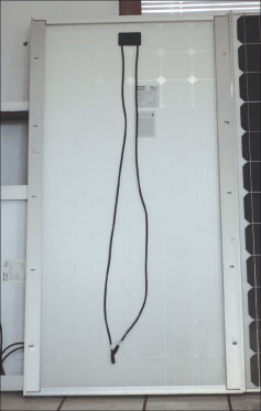
Photo 1. Modern PV module with leads and connectors
A Little History
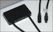
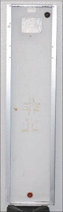
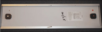
Photo 2. Early (1980s) PV module with exposed, widely spaced terminals
Historically, this exposed wiring method was allowed into the Code in 1984 because PV modules at that time had single, widely spaced output terminals diagonally opposed at opposite corners on the back of the modules [see photo 2/inset 2].
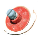
Inset 2. Exposed terminal minus the insulating cover
It was deemed too difficult (and wasteful) to use one of the conventional wiring methods to make connections to these single terminals when many of the connections were routed to another single terminal on an adjacent module only a few inches away. Subsequent to the early days, where exposed terminals and insulating caps were used, junction boxes were added at each end of the module, one for the positive and one for the negative contact [see photo 3/inset 3].
In the 1990s, both positive and negative contacts were placed in a conduit-ready junction box at one end of the modules [see photo 4/inset 4].
These types of modules with conduit-ready junction boxes are still available on special order from a few manufacturers for use where local codes require the use of conduit, particularly in commercial installations.
Workmanship Is Important

Conductor Types
The conductors permanently attached to the PV module are part of the listed module assembly and, presumably, Underwriters Laboratories (UL) has verified that the cables meet the necessary safety requirements. In most cases, the cables will be marked USE-2 or USE-2/RHW-2, and some also will be marked “Sunlight Resistant” indicating better ultra-violet capability than the basic USE-2, which is tested for UV resistance but not marked as such.
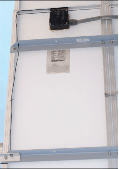
Photo 4. Special order PV module with conduit-ready junction box
PV modules are connected in series (called strings) and, after making anywhere from 4 to 24 series connections, the positive and negative conductors at the ends of the string are some distance apart. In order to bring these two points to a common location, single conductor wiring is again used. Although USE, SE, and UF cables are allowed by Section 690.31, the installer typically uses a USE-2 or USE-2/RHW-2 cable to get both the negative and positive negative conductors to a common junction point in the PV array. At this point, the exposed conductors are transitioned, using a junction box to one of the common wiring methods found in chapter 3. Don’t be misled by extraneous markings like MSHA and DLO as shown on the cable in the lead-in picture. This sunlight-resistant RHW-2 cable is not allowed by Section 690.31 for exposed, field-installed, PV module interconnections.
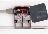
Inset 4. Junction box, both polarities
Since the environment is hot and wet on exposed roofs, usually THHN/THWN-2 or RHW-2 conductors are installed in conduit. EMT is commonly used and, where allowed by local codes, RNC may be used. In some cases, LNFC has been used and when properly attached to the supporting structure may be acceptable. A discussion of the routing of this output circuit may be found in the “Perspectives on PV” in the May/June 2007 IAEI News.
In NEC-2008, cable types USE, UF, and SE are being removed from Section 690.31 due to temperature limitations and availability in the needed sizes (10, 12, and 14 AWG) for the module interconnections.
A new PV conductor will appear in NEC-2008 in Section 690.31. It is mentioned in the comment for Section 690.35 in the 2005 NEC Handbook. This is a single-conductor cable designated “PV Wire,” “Photovoltaic Wire,” “PV Cable,” or “Photovoltaic Cable.” This cable will have an insulation that is thicker than the insulation on USE-2 (conduit fill will have to be calculated), it will be marked “Sunlight Resistant,” and it will have the necessary flame retardant and smoke properties that will allow it to be used inside buildings in conduit. This cable will be one of the wiring methods required when the PV array is operated in an ungrounded manner in PV systems that use the new transformerless inverters. See Section 690.35 for the current requirements for such systems.
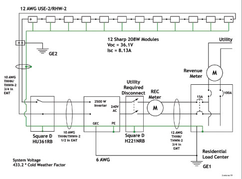
A Typical System
Conductor Ampacity
The module short-circuit currents may range from 1 amp to about 17 amps (in unusual cases). The larger 300+ watt PV modules have short-circuit currents approaching 12 amps. The ampacity of the attached and any field-installed cables should be 1.56 times the module short-circuit current (Isc) after the conditions of use are applied. In most cases, the factory-attached cables have sufficient ampacity. However, in very hot climates, the ampacity calculations should be checked. The ampacity of these conductors in free air should be evaluated using Table 310.17.
Equipment Grounding Conductors
Equipment grounding conductors connected to the PV module frames should be sized at 1.25 times the module short-circuit current (Isc). On large PV arrays, where fuses are used to protect these conductors, Table 250.122 can be used. This will result in a smaller, but adequate, equipment-grounding conductor than will be calculated using the 1.25 Isc value.
INSPECTION AREAS REQUIRING ADDITIONAL ATTENTION
Inspectors have seen the following problems in non-code-compliant installations.
Common Sense and Durability
The exposed, single-conductor cables should only be used for module interconnections. They should not be run across the roof away from the PV array, but should be transitioned at or under the PV array to another wiring method found in chapter 3 that is appropriate for the conditions of use.
Cables Like It Hot
The modules may operate up to 80°C and wiring touching or near the backs of these hot modules should have 90°C-rated insulation. The outdoor environment is a wet environment so “-2” conductors should be used that have a 90°C, wet–rated insulation both in and out of conduit.
Conduits in sunlight on roofs are going to be hot. See fine print note 2 for Section 310.10 in NEC-2005, and also see proposals in this area for the 2008NEC. An added 17°C to the average high temperature will be the minimum addition to the ambient temperature inNEC-2008. In areas where average high ambient temperatures of 40°C (104°F) are experienced, then conduits are going to be operating at least at 57°C. Appropriate temperature deratings may dictate the use of larger conductors than have been used previously to accommodate the reduced ampacity at the higher temperatures.
Grounding—Critical
Module grounding deserves at least a book by itself. With PV modules serving as power sources that will be generating hazardous voltages for the next 40–50 years, individual module grounding is a critical issue. This is particularly important since the module frames are difficult-to-ground aluminum and should remain solidly grounded for the life of the module. A ground fault in a module could energize an ungrounded frame at dangerous voltages if the module were still connected to the rest of the PV array while the module is being removed or otherwise serviced. The old, old Code requirement of connecting the ground first and disconnecting it last must certainly apply to PV modules.
Module Protective Fuse
The backs of all listed PV modules are marked with a value of a “Maximum Series Fuse” or similar wording. The overcurrent device, where required and used, protects the internal module conductors from damage from overcurrents that could be forced through the module from external sources. While many residential PV systems do not require overcurrent protection in the dc circuits, the larger commercial systems usually do require dc overcurrent protection. This will be the subject of another “Perspectives on PV.” The Code requires that any overcurrent device installed in the output of a module be rated for 1.56 Isc. There are a few modules being made (for unknown reasons) that have a maximum series fuse value of less than 1.56 Isc. This poses a Code quandary. Section 690.8 says use a fuse rated at 1.56 Isc, but Section 110.3 says to follow the product labels. Any inspector seeing such a module should report the problem to UL through the AHJ channel on the UL web site.
Summary
PV module wiring can indeed pose questions. However, the basic requirements can be found in Article 690 and as soon as those curious currents travel away from the PV array, they are contained in wiring systems familiar to all inspectors. Don’t forget, it is a hot and wet environment.
For Additional Information
If this article has raised questions, do not hesitate to contact the author by phone or e-mail. E-mail: jwiles@nmsu.edu or phone: 505-646-6105
A color copy of the latest version (1.6) of the 150-page, Photovoltaic Power Systems and the 2005 National Electrical Code: Suggested Practices, published by Sandia National Laboratories and written by the author, may be downloaded from this web site: http://www.nmsu.edu/~tdi/Photovoltaics/Codes-Stds/PVnecSugPract.html
The Southwest Technology Development Institute web site maintains a PV Systems Inspector/Installer Checklist and all copies of the previous “Perspectives on PV” articles for easy downloading. Copies of “Code Corner” written by the author and published in Home Power Magazine over the last 10 years are also available on this web site: http://www.nmsu.edu/~tdi/Photovoltaics/Codes-Stds/Codes-Stds.html
The author makes 6–8 hour presentations on “PV Systems and the NEC” to groups of 40 or more inspectors, electricians, electrical contractors, and PV professionals for a very nominal cost on an as-requested basis. A schedule of future presentations can be found on the SWTDI web site.