Significant growth in optional standby systems for commercial applications is being driven by the demand for electrical power to be present that will ensure continuity of business activities. Concerns stem from weather related outages to other reliability issues that can result in the loss of electric utility of a building, communication center, or process. Loss of power may impact food storage, or simply stop the cash register at the local home store. Even though most of those you ask will refer to the alternate power sources as emergency power, it becomes clear that an alternate source (generator) and connection with manual transfer equipment will not serve as an emergency source of power. Systems that are not tied to life or public safety areoptionalstand-by systems. These systems are considered optional despite the fact that without this alternate source, a bank, airline reservation system, or gas station would no longer be able to serve its customer.
Transfer equipment can range from an extremely simple mechanical interlock to very complex multi-circuit breaker transfer schema. This document is Part I of a series of articles that will explore various transfer equipment configurations in an effort to assist the electrical industry in the understanding of these systems and to provide guidance for the AHJ in reviewing the installation in order to grant approval of the transfer equipment.
Installations are expanding from the normal (utility) main breaker and feeders systems to include an on-site or portable roll-up generator. In fact, some installations will have both an on-site generator and provisions for a portable generator as a second level of back-up power. A quick review of the scope ofNECArticle 702 definesoptional standby systemsas “those systems intended to supply power to public or private facilities or property where life safety does not depend on the performance of the system. Optional standby systems are intended to supply on-site generated power to selected loads either automatically or manually.
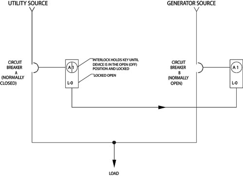
Figure 1. Key Transfer Sequence: Current Condition – Utility source feeding load – Breaker A Closed, Breaker B Open, Key A1 held in Breaker A. Desired Condition – Generator source feeding load – Breaker B Closed, Breaker A Open. 1) Open Breaker A and Rotate Key A1 to Lock Breaker Open – Key is now free. 2) Remove Key A1 from Breaker A and insert key into lock on Breaker B. 3) Rotate key A1 to unlock breaker B, Key A1 now held captive. 4) Close Breaker B. 5) Reverse procedure to restore service to breaker A.
“FPN: Optional standby systems are typically installed to provide an alternate source of electric power for such facilities as industrial and commercial buildings, farms, and residences and to serve loads such as heating and refrigeration systems, data processing and communications systems, and industrial processes that, when stopped during any power outage, could cause discomfort, serious interruption of the process, damage to the product or process, or the like.”
Fundamental Safety Application
Traditionally, optional standby systems were used in industrial installations where the availability ofqualified personneland an on-site generator was more likely to be present. In the event the normal utility source is lost, some or all of the load could be manually or automatically transferred to the generator, based on the generator size and customer needs. A fundamental safety concern for the transfer equipment is the prevention of both electrical sources from connecting to the load at the same time. If allowed, the generator could reverse feed the utility system creating hazards for utility and other personnel and also possibly damaging the generator.NEC702.6 specifies that the transfer equipment shall be installed to prevent paralleling of the normal (Utility) and alternate (Generator) sources, unless the equipment is designed for parallel operation and meets the requirements of Article 705.NEC702.6 only contains one very restrictive exception to the transfer equipment requirement.
“Exception:Temporary connection of a portable generator without transfer equipment shall be permitted where conditions of maintenance and supervision ensure that only qualified persons service the installation and where the normal supply is physically isolated by a lockable disconnecting means or by disconnection of the normal supply conductors.”
In contrast to industrial installations, most commercial installations do not have qualified personnel or on-site maintenance with supervision. It is important for these installations that the transfer equipment and process be simple, easy to understand, and provide all of the requirements specified in theNEC. Automatic transfer equipment provides a robust and reliable solution but many times these systems add more features, complexity, and cost than the installation requires. Where manual transfer equipment is acceptable, there are several methods that can be used. One such method of meeting the transfer equipment requirements is the use of an interlock system.
The Key Interlock System
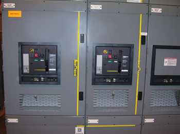
Figure 2. Key interlocks installed on devices located in different compartments or enclosures
A key interlock system is one that employs one or more key interlocks installed on associated equipment to permit operation of the equipment only in a pre-arranged sequence. Key interlocking associated equipment differs from ordinary locking methods by requiring that the key be retained in the lock in either the locked or unlocked position depending upon the system design. The retention of the key in the interlocked devices forces pre-defined equipment operation and does not depend upon operator memory or skill. For an optional standby system, key interlocks are installed on the normal source breaker (Utility) and the alternate source breaker (Generator) which will allow the transfer of load from one source to the other with a defined sequence of steps. For this system, the key is held in the normal source breaker until the breaker is opened and locked. Once locked the normal source breaker cannot close. The alternate source breaker is normally in a locked open state and cannot be unlocked without the key from the normal source interlock. Figure 1 provides each step of the transfer sequence.
This solution is desirable because of the ability to mechanically lock the disconnecting device to prevent paralleling of sources, because it is a simple transfer operation which forces a correct sequence of operation, and because of its relatively low cost. Another benefit of this approach is the adaptability of key interlock systems to other power system configurations such as Main-Tie-Main and Main-Tie-Generator. This flexibility means that the devices used to make up the transfer equipment do not have to be physically in the same compartment or enclosure. Examples of those applications are demonstrated in figures 2 – 4.
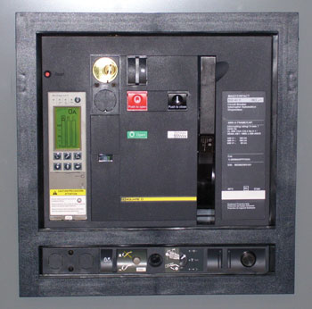
Figure 3. Example of key interlock mounting location in a circuit breaker device
It is also possible that where existing equipment is installed and generator provisions are being added, key interlocks are usually easily field installable. However, that leads us down the path of understanding how to determine if the installation is acceptable for approval by the plan reviewer or electrical inspector.
Equipment Approval
NEC702.4 requires that transfer equipment be approved for the intended use. In order to guide this discussion, we need to sort out the terminology with regard totransfer equipmentandtransfer switch. Transfer equipment is a very broad term used to permit the use of switchboards, double throw switches, panelboards and other equipment configurations to transfer power. The termtransfer switchis very specific and although not distinct in difference in Article 702, Article 700 establishes a solid distinction where 700.6 in general discusses transfer equipment and a subsection beneath, 700.6(C), establishes requirements specific for a transfer switch. It is important to understand this distinction as the 2008NECrequires the transfer switch, rated 600 V or less, to be listed.
There are at least three methods to assist in the approval process. The first is product listing. Listing agencies evaluate transfer equipment using a number of different standards, such as UL 67 Panelboards, UL 98 Enclosed Switches (double-throw switches), UL 891 Switchboards, or UL 1008 Transfer Switch Equipment. The electrical equipment will have a listing mark that designates the primary use of the equipment. Since the panelboard standard includes special testing requirements, we would not list a panelboard as a transfer switch. This testing would be missed if the panelboard was listed to a transfer switch standard. However, equipment may come marked “suitable for use in anNEC702 application” such that the installer and inspector understand that it can be used in that application.
The transfer equipment, such as key interlocks, may be installed in the field. The language inNEC702 is very specific to require approval and not listing in order to permit the modification of equipment in the field. However, if the inspector is concerned about a field installed assembly that is not identified for use with the equipment, it may require a third party to perform a field evaluation of the installation to ensure compliance with basic standard’s requirements.
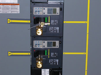
Figure 4. Key interlocks installed on devices located in the same compartment or enclosure
Finally, the inspector can choose to approve the system with or without a listing mark. Consider a facility that has multiple sources and equipment that is located in various locations of the building, or maybe key interlocks on two different manufacturer’s switches under a trough. It is reasonable to expect that an electrical inspector could approve such an installation without third party evaluation.
Plan Review and Inspection
Optional standby system installations require transfer equipment. Key interlocks play a significant role to ensure electrical safety across the country and will insure proper transfer operations. Transfer equipment utilizing key interlocks provide positive locking operation, are easy to install and operate, and forcibly direct a correct sequence of operation. However, there are a few key items to ensure compliance and reach approval of the installation.
1. Is the equipment listed or marked to identify it for use in an NEC 702 transfer application?
2. If existing equipment is involved and a key interlock is being added, understand the retro fit activity so the parties involved will understand if a field evaluation may be necessary. Is it a kit provided by the equipment manufacturer? Is this simply a set of interlocks being installed in the field but not endorsed by the manufacturer of the equipment?
3. What type of system is being considered? Is it a direct mechanical interlock between two switches/circuit breakers? Is a key interlock being used?
4. Understand that any additional keys beyond those required to operate the interlocks will defeat the transfer system. Understand if additional keys are provided from the manufacturer of the equipment or the key interlock provider. Are additional keys going to exist on the premises of the installation? If so, ask to understand if the extra key is secured. If it cannot be demonstrated that additional keys can be secured, then destruction of the extra keys may be necessary to grant or obtain approval.
5. If there are any questions about the transfer operation, walk through the operation of the key interlocks during inspection.
The safe transfer of electrical power is the objective; avoiding the inadvertent interconnection between sources which could back-feed a system and injure personnel. Once again, key interlocks have been the cornerstone of a safe, simple, and reliable means of transfer for decades. There are other options and Part II will explore more equipment and provide additional guidance and questions to ask in addition to considerations for those systems.