A former student called me to ask how to size a new generator for a facility. He said the calculated load would be 1200 amps at 277/480 three-phase four-wire. It would be used for supplying power when the normal electrical supply system is interrupted. This would include lighting for general illumination, for life support equipment found in operating rooms and for other electrical emergency systems necessary for safety and health of the occupants.
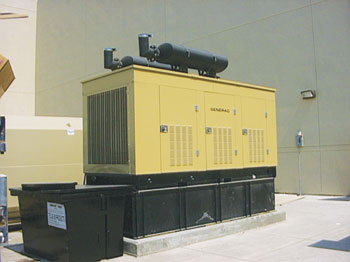
Outdoor Generator
Since the building houses a state government entity it would be necessary to conform toNEC-2008 Article 700; however, Article 701 is similar in the provisions as set forth in that article. The big difference is found in Part III of 701 and 700, Sources of Power. Section 701.11 requires a maximum time period of 60 seconds for legally required standby power after normal power supply is lost. Section 700.12 requirement for emergency systems is to not exceed 10 seconds. Keep in mind there are other significant differences/similarities within the two articles.
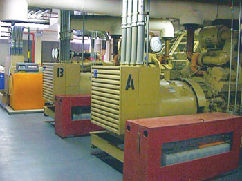
Generators are sized based on kW ratings
Now, back to sizing the generator; the type of source fueling the generator is unknown and will be a factor in the actual output of the generator. Perhaps a good guess would be natural gas, LP gas, gasoline, or even fuel cells, assuming there is no other emergency source from the local electrical provider, as permitted by 700.12(D). Generators are sized based on kW ratings. Since the ampacity and the voltage of the load being served is known but not the kW rating then it would be necessary to apply a mathematical formula to arrive at a solution in order to properly size the generator for the load being served.
Applying the formula to find kilowatts:
(I x E x 1.732) / 1000
We must understand the symbols of the formula: E is electromotive force, or voltage. I represents intensity or current. If power factor (PF) is known, use it in the formula; if not, disregard. If the voltage is three-phase, the square root of three (1.732) must be included in the formula which will yield a divisor based on the voltage. Thus, the formula we are using in this example is:
(1200 x 480 x 1.732) / 1000 = 997.63 kW
or rounded up to 1000 kW (1 MW) generator (perhaps a standard size).
Now, to do a checkpoint and verify that it has the ampacity to handle the load, multiply the 1000 kW times 1,000 = 1,000,000 VA or 1 MVA. Using a divisor of 831.36 (480 x 1.732 = 831.36) divide it into the 1,000,000 MVA = 1,202.84 A. Yes, the 997.63 kW or 1000 kW generator is sufficient for the installation. This would include any continuous duty loads. Section 700.5(A) states that the emergency system shall have adequate capacity and rating for all loads to be operated simultaneously.
Including the power factor
If the power factor is known, it must be included in the formula. In the example above it is assumed to be unity (100 percent or 1), although not included in the formula. If the power factor is less than 100 percent, then insert the percentage of the power factor into the formula, example:
(E x I x PF x 1.732) / 1000
Now, assume 67% for the power factor. Formula is to include this factor, example:
1200 x 480 x .67 x 1.732 = 668,413.44 VA.
Obey Ohm’s law and divide the voltage divisor 831.36 (480 x 1.732= 831.36) into the 668,413.44 VA = 804 amps. This is a remarkable difference versus the 1202.84 amperes when the power factor was unknown.
NEC 220.12 FPN refers to Table 220.12 to be used for occupancies listed therein for calculating the minimum lighting load with a caveat of 100 percent power factor and may not provide sufficient capacity for the installation contemplated. All the load calculations examples in Annex D are presumed to have the same power factor.
Sizing the conductors
Using the nameplate current rating of the generator, conductors shall be calculated at not less than 115 percent of that rating per 445.13. Unless the design and operation of the generator prevents overloading, in which case ampacity of the conductors shall not be less than 100% of the nameplate rating of the generator (445.13 FPN). Thus far we have arrived at two ampacities for the generator in our example. The first calculation, without a power factor, yields an ampacity of 1,202.84 amps, or rounded up to 1,203 amps. Complying with 445.13, the nameplate current rating shall be multiplied by 115 percent: 1,203 A x 115% = 1,383.45 amperes for the ungrounded conductors. This would necessitate installing a multiple parallel because of the total ampacity. Neutral conductors are sized according to 220.61 and may be reduced under certain conditions.
Historical background on sizing conductors
A visit to the archives revealed a discovery of the National Board of Fire Underwriters (NBFU) National Electrical Code 1962; in that edition, only nine sections made up the entire content of Article 445, only one and a half pages, and were dedicated to generators.1 Regarding the neutral sizing per 445-5 of NEC-1962, “Neutral conductors shall be the same size as the conductors of the outside legs.” No reduction was permitted for neutral sizing. Also, there was no mention of terminating at an overcurrent device. No exception(s) followed. An interesting side note to the 1962 edition is its size: 4 ¼” wide and 6 3/8” long with only 417 pages, excluding the index, bound together by what appears to be brown kraft paper. It is small enough to fit into the back pocket of an electrician’s bib overalls and within arm’s reach.
This wording remained unchanged untilNEC-1978, at which time 445-5 stated, “… to the first overcurrent device…” and was included along with new Exceptions No. 1 and No. 2. Exception No.1 allowed using 100 percent of nameplate current rating if the generator had means of an overcurrent device that was connected directly to the manufacturer’s leads. Still further silence about neutral conductor sizing except as indicated in the 1962 edition.
Not untilNEC-1981 and Section 445-5 was anything prescribed giving a specificCodesection for sizing the neutral conductor. Sections 220-22 and 250-23(b) ofNEC-1981 finally answered that question regarding sizing the neutral conductor.
Parallel raceways
Now, back to our calculation; assuming a power factor of 67% as indicated in the formula results in an ampacity of 804 amperes. Again, complying with 445.13, the nameplate current rating shall be multiplied by 115%:
804 A x 115% = 924.6 or 925 amps
for the ungrounded conductors;
and comply with Section 220.61 to size the neutral conductor. Using either calculation, a multiple parallel would be necessary.
The exception to 445.13 states that where the design and operation of the generator prevent overloading then only 100% sizing of conductors is necessary: 1,202.84 amps without a power factor and 804 amps with a power factor.
Selecting conductors for our generator would be calculated by using multiple parallel runs of a raceway enclosing the conductors. The number of parallel raceways would depend on the size of the conductors. Section 310.4 details conditions for conductors in parallel. Once the ampacity of the conductors is determined then we must consider selecting overcurrent protection. Because the calculations are over 800 amps, we turn to 240.4(C).
The basicCoderule of rounding up for overcurrent protection is not permitted for devices rated over 800 amps.
Looking back at our first calculation of 1202 amps and paralleling five raceways (1202 amps divided by 5 = 240.4 amps per run) will require size 250 kcmil copper conductors found in the 75°Celsius column of Table 310.16 to equal 255 amps, [making sure that we visit 215.2(A) FPN No. 2 if we have a long feeder run for voltage drop]. A quick checkpoint to verify adequacy of the conductors: 5 x 255 = 1275 amps. This calculation assumes that the manufacturer has provided overload protection at the generator. If not, it would be necessary to increase 1203 amps by 115% and thus yield larger conductors and an overcurrent device setting that may not be of a standard rating.
Selecting overcurrent protection device
For selecting an overcurrent protection device it is necessary to look at the standard ratings of devices found in 240.6(A). Section 240.4(C) states that the ampacity of the conductors shall be equal to or greater than the rating of the overcurrent device. Therefore, this installation would require a standard 1200-amp overcurrent protection device because the sum of the conductors is 1275 amps.
Providing backup electrical power is, for some dwelling premises, an option. TheNECdoesn’t specifically require that a generator installation be made mandatory in dwellings and be used entirely as a backup power source for lighting, heat or air conditioning or, in some homes, life-saving equipment. With our insatiable appetite for electricity, perhaps one day in the future there will be a newNECarticle making it mandatory that every dwelling have a built-in generator installed, sized and wired by an electrician with an approval from the local authority having jurisdiction.
Perhaps one day in the foreseeable future we will find neatly tucked away behind the flowers, shrubs and other blooming plants, a plant of a different kind: a generator plant for the home. This one doesn’t need any water or grooming to survive. Coming soon toNECChapter 7, Special Conditions, add new Code article: Home Power Plant.
References
1 NFBU No. 70, 1962National Electrical Code, Standard of the National Board of Fire Underwriters for Electric Wiring and Apparatus as recommended by the National Fire Protection Association, American Standard. Approved July 24, 1962 by American Standards Association, Dated October 1962.