It’s Complicated — you’ve probably seen this witty movie about divorce. Motor wiring rules are complicated too, but not nearly as amusing as the movie. This article reviews our complicated rules for motor supply conductors.
When wiring is installed directly into a motor terminal box, Rule 28-104 tells us that the minimum conductor insulation temperature must conform to the motor’s insulation class. Rule 28-104 refers us to Table 37, which provides conductor insulation specifications for motor classes A, B, F and H. Motors are further divided into two categories, totally enclosed non-ventilated and all the rest.
The motor nameplate identifies the motor’s insulation class and whether the motor is totally enclosed non-ventilated (TENV) or another type. According to Table 37, for an insulation Class B motor, the minimum conductor insulation should be 75°C, except for a TENV motor, for which 90°C insulated wiring should be provided.
But wait, there are further complications. For wiring insulation greater than 75°C, Rule 28-104 demands that wiring between the motor and its termination point (switch, motor starter, and so forth), must be at least 1.2 m in length and the point of connection must not be closer than 600 mm to the motor. And for motors 100 HP and greater, the conductor termination point must be located at least 1.2 m from the motor.
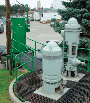
Photo 1. Municipal sewer ejection pump motors.
But we’re not through yet! Table 37 gives us conductor insulation temperature values for ambient temperatures only up to 30°C. For ambients greater than 30°C, the rule requires that we add the difference between the expected ambient temperature and 30°C to the conductor’s temperature rating as determined from Table 37. If the expected ambient at the motor location is 40°C, and then we must add 10°C to the conductor data derived from Table 37.
But yet one more thing. Except for Class A motors, Rule 28-104 requires that motor supply conductor ampacities be based on their 75°C insulation ratings. In other words, even though higher insulation temperatures have been selected, this rule specifies that minimum conductor ampacities must be based on the lower ampacities provided by the 75°C columns of Tables 1 to 4.
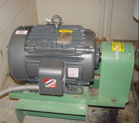
Photo 2. Typical motor wiring method.
Moving right along, Rule 28-106 and Table 27 remind us that there are two additional types of motors, continuous duty service and non-continuous duty service. Continuous duty service applies to motors that run continuously, loaded or unloaded. The minimum conductor ampacity for a continuous service duty motor must be no less than 125% of the motor full load amperes. Table D16 lists minimum motor conductor ampacities for motors up to 500 full load amperes.
Non-continuous duty service describes motors, those that don’t run continuously, such as an elevator motor. Table 27 separates the classifications for non-continuous duty service further into short time, intermittent, periodic and varying duty, along with examples for the various categories. The table further breaks down duty service into four duty cycles, 5-minute, 15-minute, 30-and 60-minute, and continuous. Minimum conductor ampacities are based on service duty classification, expected rated operating cycles and calculated as a percentage of the motor’s nameplate current rating.
I think you will agree, it’s complicated. As with previous articles, you should always consult the electrical inspection authority in each province or territory for a more precise interpretation of any of the above.