The rooftop temperature adders in NEC310.15(B)(3)(c) were first included in the 2008 NEC. The proposal to include this requirement was based on a study that showed increased temperatures in conduits on rooftops in direct sunlight. However, there remained unanswered questions for the Southern Nevada Chapter of IAEI; they live with extreme temperatures, and yet installers and inspectors have not seen evidence of failure related to rooftop installations. Since the impact on conductor sizing due to this requirement is significant in the Southern Nevada area, the Chapter funded an experiment to gather more information about rooftop electrical installations exposed to direct sunlight.
In conjunction with SouthWest Electritech Services, a third party independent electrical testing firm, Chapter members designed a test setup to determine if actual electrical installations on rooftops experienced the damage to conductors reported to Code-Making Panel 6 in the 2008 NECdevelopment process. The conductor sizes used were based on NECrequirements, but without the temperature correction factors required by 310.15(B)(3)(c).
Test Setup Installation and Data
In order to capture data during the hottest part of the year, the test setup was installed July 7, 2012; data was collected and analyzed for a two-month period. The test period captured data during the hottest days of 2012, which was reported to be the hottest summer on record for Las Vegas. Licensed electricians installed the electrical conductors and thermocouples. Southwest Electritech Services employees installed the data loggers, current meters and recording software.
The test installation was located on a facility that is a two-story warehouse with office area on the first floor (occupying about 25% of the first floor). The construction is concrete tilt up with a wood truss built up roof, using asphalt rolled roofing. The second story was not in use throughout the duration of the testing, and therefore was not conditioned.
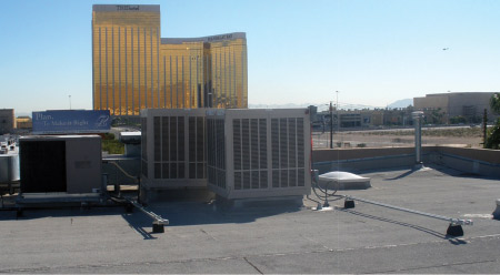
Photo 1. Rooftop installation for temperature experiment in Las Vegas
Temperature data was collected in three conduit locations. Since the electrical equipment was already in place, an additional 20 feet of EMT was added to each circuit (photo 1) to allow for the installation of the monitored conductors and thermocouples. The runs were installed running east to the west in a location chosen to get maximum sunlight exposure during the hottest portion of the day.
Two thermocouples were installed in conduits with wire that was unloaded and attached to an evaporative (swamp) cooler in two different conduit sizes. Another thermocouple was installed in a conduit with wire that was loaded and attached to an air conditioner. The thermocouples were carefully installed in such a way as to contact the conductor installation and in no way be in contact with the EMT itself (photo 2).
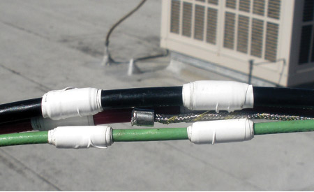
Photo 2. Thermocouple installation
The first setup had five 12 AWG conductors with THHN/THWN-2 insulation. These were installed in 10 feet of 1/2″ EMT and the return run in 3/4″ EMT. A thermocouple was installed in each of these runs. Also, a thermocouple was installed inside the disconnect of the evaporative cooler these conductors fed, and then one thermocouple was installed to measure outside ambient temperature at approximately 48″ above the roof surface, near the top of the cooler. The conduits were supported on industry manufactured roof support block approximately 6″ above the roof surface (photo 3).
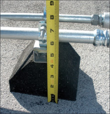
Photo 3. Height above rooftop
The second installation was connected to a 5-ton rooftop mounted all-in-one A/C unit that was in use for the duration of the test (photo 4). This unit supplies cooling to the first floor offices of the facility. It was found that this unit frequently ran for over 3 hours at a time, giving us good data on the conductors feeding it. Measuring temperature readings on the insulation of the loaded conductors provided a real world application (photo 5). Since the A/C was the only load on these conductors and ran for more than three hours at a time, it was a good test of an installation with continuous loading and without diversity.
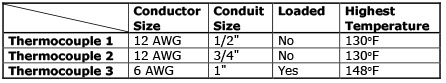
Table 1. Highest recorded temperatures for each thermocouple in conduit
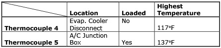
Table 2. Highest recorded temperatures for thermocouple in disconnect and junction box
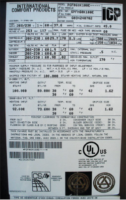
Photo 4. AC label
This installation consisted of two 6 AWG THHN/THWN-2 conductors with a 10 AWG equipment grounding conductor, installed in 1″ EMT, again on the same type of roof supports as the first installation. For this installation, a thermocouple was installed in one of the runs of the 1″ EMT, one was installed in the junction box about 18″ above the rooftop and the outside thermocouple was installed about 6″ above the rooftop so that it would have a western exposure.
Intellirent, a company specializing in electrical test equipment, provided certified, calibrated data loggers and current meters, as well as the computers and software used to download and analyze the data. Data was collected every 60 seconds by each of the data loggers for each of the measurement points (photo 6). This produced a great deal of data. In order to report meaningful information, the highest temperatures recorded each day were compared to nationally reported ambient temperature values obtained from the NOAA database. This comparison resulted in a maximum daily differential temperature.
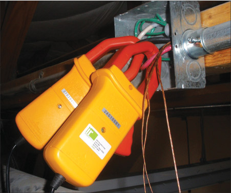
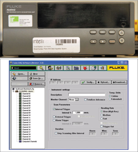
Photo 6. Data logger and software
Ambient temperature data was also collected with the thermocouples installed in two locations on the roof. In general, these ambient thermocouples recorded temperatures higher than that reported by NOAA. Since installers and inspectors will typically depend on nationally reported data, we chose to use the NOAA data to calculate the differentials. This resulted in a worse case differential than if the measurements from the ambient thermocouple installed on the rooftop were used.
Results
During the experiment, it was found that on an actual rooftop in Las Vegas in an actual installation of conduits with wires (both loaded and unloaded), the temperatures measured did not approach the temperatures predicted by the adjustment requirements in Section 310.15(B)(3)(c). On the contrary, the average temperature differential recorded was 15°F for unloaded conductors in conduit. Since the conduits were installed approximately 6″ above the rooftop, the adjustment factors required by the values in the 2011 NEC Table 310.15(B)(3)(c) would require an adder of 30°F, twice the actual measured values.
Additionally, it was observed during this real world rooftop test that the loaded conductors never exceeded the operating temperature of the conductors or terminations during the testing. Since the originally stated reason that the additional temperature correction was added to the code was the premise that conductors would exceed their rated temperature, this testing shows that the premise was false. The highest recorded temperature was 148°F for fully loaded conductors. The maximum ambient temperature on that day was 114°F according to NOAA, resulting in a differential of 34°F for loadedconductors in conduit operating at the maximum load recorded on the air conditioning circuit (37 amps). Much of this differential was due to the heat generated by the current flowing through the conductor, not the heating of the conduit by sunlight exposure.
The conductors are rated at 194⁰ F and the connections are limited to 167⁰ F. Comparing these limitations to the measured temperatures indicates that even should the temperature be more extreme or if there was additional load placed on the circuit, the conductors and connections are unlikely to exceed their rated temperature.
2014 NEC Proposal 6-29 requested even higher values for temperature correction – for this installation, 50⁰ F would have been required. CMP-6 decided in the Comment phase to reject Proposal 6-29 in Panel Comment 6-14a. This decision was based in part on the information gathered during the experiment described in this article, which was presented to CMP-6 at the ROC meeting in December 2012.
Summary
The test results indicate that the added temperature correction values in 310.15(B)(3)(c) are unnecessary for rooftop electrical installations in the Las Vegas area. Since Las Vegas is one of the hotter areas in the country, it is likely that the correction factors are unnecessary for other areas, as well. These findings support the statement submitted by IAEI CMP-6 principal John Stacey with his negative vote to 2014 NEC Comment 6-16, which stated that “The requirement in Section 310.15(B)(3)(c) increases cost with no benefit to the safety of people or the protection of equipment, and this requirement should be removed in its entirety.”