We have finally reached the portion of the code that deals with conductors. Conductors are used on every electrical installation, so naturally we have a variety of installation conditions and a wide range of applications. Again, keeping to the scope of work for combination inspections, I will discuss only the most common installations that may be experienced by a fellow combination inspector.
Article 310 experienced a significant reorganization in the 2011 NEC. The code-making panel made the changes in order to comply with the requirements in the NEC Style Manual. These changes included renumbering and relocating many requirements and tables, so take a moment to compare the 2008 and 2011 codes.
In NEC 310.1, the scope states that this article covers general requirements for conductors, type designations, insulation, markings, mechanical strengths, ampacity ratings and uses. This is
followed by a disclaimer that this article does not apply to conductors that are an integral part of equipment. This may be the case for motors, controllers or other equipment assembled in a factory.
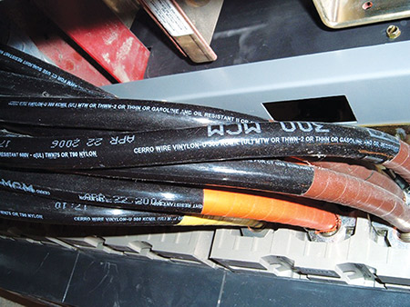
Photo 1. Example of a wire manufacturer multi-listing conductors
At this point, we need to jump over to Part III of Article 310, which is 310.104 Conductor Constructions and Applications.
This is, basically, an introductory paragraph and Tables 310.104(A) through (E). Of these, the most often used is Table 310.104(A) titled “Conductor Applications and Insulations Rated 600 Volts.” Wire is generally referred to by a letter designation, such as: TW, THW, XHHW, MTW, and so on. Please open the code book and follow along on this table. The columns will give you the maximum operating temperature, application for dry, wet and damp locations, the material of the insulations, and wire size ranges, along with other information.
For an example, let’s look at RHW and RHW-2. In the first column, you will notice that RHW is a flame-retardant, moisture-resistant thermoset insulation. It is rated for use at 75 degrees C and approved for dry and wet locations. RHW-2 is rated for use at 90 degrees C, but otherwise has the same properties as RHW. Next, let’s review XHHW-2, which is also a flame-retardant, moisture-resistant thermoset rated for use at 90 degrees C in wet or dry locations. So what is the difference? There are two differences in the table. The first is the thickness: RHW-2 has a much thicker insulation. The second is the use of a covering: RHW-2 may have an outer covering, while XHHW-2 does not. That is one reason you will never see an “XHHN”; “N” stands for a nylon covering, but XHH (or XHHW or XHHW-2) does not have an outer covering.
There is another condition that we need to cover and that is dual-rated wire, which is commonly found in the field. One of the most common is THHN/THWN-2; you will notice that these are both thermoplastic insulations; however, one is for dry and damp locations and the other is for dry and wet locations, both rated for 90 degrees C. Manufacturers will dual mark conductors which meet both standards so that they can produce one item for multiple applications. This saves them from having to run several different products and constantly changing the process from one to the other.
The letters in the wire designations represent insulation characteristics. A “T” generally means thermoplastic insulation, while X stands for thermoset insulation. One “H” means that the conductor is one level higher on the heat rating above the beginning point of 60 degrees, so one H would signify 75 degrees. A double “H” (“HH”) moves you up to the 90-degree range. The “W” in the legend gives us the approval for wet locations, and the “N” usually means a nylon outer coating. So let’s see if we can figure out what XHHW means, using these general rules. First, the “X” stands for thermoset; second, the “HH” means it is rated for use at 90 degrees C; and last, the “W” means it is approved for wet locations. Notice, however, that the Table indicates that XHHW can only be used at 75 degrees C in wet locations, so you have to be careful about using only the letters printed on the conductor. The lesson here is the letters may get you close, but you cannot assume they tell the whole story; take the time and double-check them against Table 310.104(A). Additionally, UL has a Wire and Cable Marking Guide that explains the letter designations and insulation types in depth.
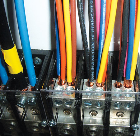
Photo 2. Conductors installation found by an inspector. For those who have been following our articles, please do some review and see what code violations you can identify.
In several references above, we have mentioned temperature ratings; these temperatures are the maximum temperature that a conductor insulation will reach under full load at a stated ambient temperature. All the values stated above are in Celsius, so to put it into something we are more familiar with, a 90 degree C conductor is good for 194 degrees F. If a conductor is exposed to a temperature higher than that for a prolonged period of time, the insulation cannot be depended on to protect the conductor and will, in all likelihood, start to breakdown.
Jumping back to Part II of Article 310, we cover Installation of conductors. First, we have Uses Permitted in 310.10, which is divided into eight sections lettered (A)– (H). These include dry, dry and damp, and then wet locations. As we have mentioned above, the properties of certain insulations are made to withstand exposures to various conditions; for descriptions of these locations, please refer back to the Article 100 definitions under “Locations.”
In 310.10(E), the code covers the application of shielding. This is usually not in the scope of the work that is performed by the everyday combination inspector. Shielding is applicable to voltages over 600 volts, and we have mostly kept this series of articles to 600 volts and below.
The next two sections cover direct burial and corrosive locations. This is simple, you must have conductors that are identified and suitable for the conditions under which they are installed. If there is an unusual condition, you may have to ask the installer, engineer or manufacturer for information indicating that the conductor or insulation is suitable for the installation conditions.
Conductors in Parallel is covered in 310.10(H). Often when working with higher ampacities, we find it to be cumbersome and expensive to keep increasing the size of the wire and conduit. The solution is often to use multiple runs that are connected to a common location on each end. Notice in the 2011 edition of the code that much of this section is highlighted gray, indicating new or revised text. The change here was that the previous code stated that you were permitted to parallel conductors 1/0 AWG and larger; however, it didn’t specifically prohibit you from paralleling smaller conductors, which was the intent and the way it was enforced in all my years of enforcement. However, that’s not what the actual language said, and ambiguous language cancause enforcement issues; therefore, in the 2011 code it was made clear that you are only allowed to parallel conductors 1/0 AWG and larger.
There are some very critical and specific requirements to be followed for parallel runs. These are covered in 310.10(H)(1) through (6). We will cover these in detail. Each conductor for the same phase, polarity, neutral, grounded or grounding conductor must be of equal length, consist of the same metal, be the same size in circular mil area, have the same insulation type and be terminated in the same manner. These items are required and should be on the top of every inspector’s mind when encountering parallel installations.
I have seen or had calls on installations where these conditions were not followed, and the issues that result are unequal loading on the conductors and overheating causing damaged equipment and conductors. Keep in mind that when we say terminated in the same manner, we mean exactly the same lugs, number of bolts and size of the lugs, etc.
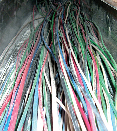
Photo 3. After reading 310.15, how would you derate the conductors in this wiring gutter? Hint, also see 366.22.
Continuing with parallel installations, if the conductors are run in separate cables or raceways, the cables or raceways shall have the same number of conductors and shall have the same electrical characteristics. This means that you cannot have one run in PVC conduit and the other in rigid galvanized conduit as these have very different electrical properties. Parallel runs are also subject to any derating conditions found in 310.15(B)(3)(a), which we will cover shortly.
In 310.10(H)(5) and (6), we cover the equipment grounding conductors and equipment bonding jumpers. The equipment grounding conductors (where used) shall be sized according to 250.122, which is based on the overcurrent device which is feeding the conductors. The equipment bonding jumper shall be sized according to 250.102, which is based on 250.66 according to the size of the conductors used.
Before we jump into temperature limitations, we need to start with the tables related to 310.15(B). There are six tables here starting with 310.15(B)(16). I know some of you may wonder why we start with the first table numbered 16; this is for ease of use, because this table was previously known as 310.16. It was changed to comply with requirements in the NEC Style Manual, which requires tables referenced within an article to have the same number identification as the article. There never has been a clause numbered 310.16, so for us long-time code users, the code-making panel decided to keep the 16 present in the table designation. This also helps to facilitate the thousands of references in other materials within the industry that reference ampacities.
Please read the differences between the headings of each of the tables found in 310.15(B); you will notice that one table may apply to conductors in a raceway; another may give values related to conductors run in free air. Some tables may refer to different conductors rated for a higher temperature. The table that you will use the majority of the time is 310.15(B)(16). So, you might as well tab that page or dog-ear it so you can find it quickly. This table covers the common conductors used in construction; you will notice that it is split down the middle, with copper conductors on the left, and aluminum and copper-clad aluminum on the right side. For those who have never heard of copper-clad aluminum, it is aluminum conductor that has an outer coating of copper.
The last part of 310 we are going to cover and the most laborious part is temperature limitations of conductors. These factors take into account the number of conductors within a raceway, the location of the conductors, and what they are exposed to that may increase the ambient temperature around them.
So let’s start in 310.15(B)(3)(a), where we cover the number of current-carrying conductors in a raceway or cable. You will notice in the title of Table 310.15(B)(16) that it is based on three current-carrying conductors, so if we exceed that number we have to do an ampacity adjustment. The idea here is that when conductors carry electricity, they heat up according to the load. Since our table has only taken into account three conductors, we have to lower the values allowed when we use additional current-carrying conductors. The table to reference is Table 310.15(B)(3)(a), where we find that if we use 5 current-carrying conductors, we would have to apply an 80% correction factor to the values given in 310.15(B)(16). So, a 2 AWG aluminum XHHW-2 conductor would be good for 80 amps instead of 100 amps if there were only 3 conductors. A note that has to be covered here is found in the second paragraph of 310.15(B), which states the adjustment or correction of a conductor is allowed to be applied to the rated temperature value of that conductor. So if you have a conductor which falls in the 90 degree column, then you can start with that ampacity value, as long as
the final calculated ampacity value does not exceed the temperature limitations of the termination points.
If your conductor starts in the 90-degree column and you derate it to a value that exceeds the temperature rating of the equipment (which is generally rated at 60 or 75 degrees C), you are not allowed to use that conductor at a value above the termination ampacity. So for the example of 2 AWG XHHW-2, if you derated it from 100 amps to 80 amps, but we were terminating it onto equipment that was only rated for 60 degrees C, we wouldn’t be allowed to run it at an ampacity higher than 75 amps. This works throughout the ampacity adjustment portion of the code; however, because you can start at the actual conductor temperature rating, it frequently allows us to run smaller conductors overall due to the improved insulation properties of the higher rated conductors.
Now that we have the number of conductors in a raceway out of the way, we can jump back to the Ambient Temperature Correction Factors found in 310.15(B)(2). You will notice that at the top of each of the ampacity tables, in the heading it states that the ampacities are based on a certain ambient temperature, either 30 degrees C or 40 degrees C. If the conductors are exposed to temperatures other than the stated ambient temperatures that the tables are based on, we must adjust the ampacities accordingly. The code has two temperature adjustment tables, one based on 30 degrees C and the other based on 40 degrees C, and these are Tables 310.15(B)(2)(a) and (b). When you look at these tables, you will notice that the column headings are conductor temperature ratings. After you find the conductor temperature rating, you go down that column to the row that applies to your ambient temperature exposure. This can go both ways; if we look at the 30 degree C table and your installation is in an environment that is between 11 and 15 degrees, the wire will be able to handle 22% higher current than it would at 30 degrees C. Conversely, if you have your installation in 100 degrees F (which is equal to 38 degrees C), then you have to adjust the allowed ampacity by a factor of 82%.
Some interesting items regarding these factors are covered in 310.15(B)(3)(3). One item states that the adjustment factors do not apply to underground conductors entering or leaving an outdoor trench if they have physical protection in the form of various conduit types listed, as long as the length of the conduit does not exceed 10 feet. There are other modifications in this section, be sure to read through the entire text of 310.15(B)(3)(b).
Another consideration relates to having different portions of the conductor run though different temperature environments. For example, if you have a raceway that is run inside a facility that has a controlled temperature and then it penetrates the roof to feed a piece of equipment, we have to take the higher of the two ambient temperatures for derating, unless the higher temperature exposure is not more than 10% of the total run or 10 feet, whichever is less. So if we have an 80 foot run, only 8 feet can be exposed to the higher temperature, or we would have to apply a temperature correction. If the run is 100 feet or longer, the maximum exposure before temperature correction would be 10 feet. This is covered in 310.15(A)(2) Exception.
There are several other items regarding temperature correction of conductors within Article 310; however, in the interest of time and recognition of the situations that are most commonly found during combination inspections, I have just touched on the most significant items. Please take the time to crack open your code book and review some of these other applications that may apply in your specific inspection areas.
The last item for this article is 310.15(B)(7), which is a special table related just to dwelling services that are 120/240-volt single-phase. The table related to this article allows a specific wire size based on the rating of the service or feeder. This is a very special allowance which is based on the fact that in dwelling units we have very conservative load calculations versus the actual demand at any time in a dwelling. As such, we know that the actual loads on dwellings are much lower than the calculated load, and this table takes that into account. For instance, a 3/0 AWG copper conductor could be used for a 200-amp load based on the 75 degree C column of Table 310.15(B)(16), and in the dwelling table you will find it is allowed to be used for a 225-amp service.
As I said earlier, this part of the code is the most frequently used due to the fact that every installation has conductors. As we install these conductors, we have to follow the various code requirements from Article 310 that apply based on our unique installation conditions. Thanks for taking the time to read this article, and I hope this helps to improve your code knowledge and inspection ability.