What are the criteria for connecting more than one motor on a single branch circuit overcurrent device?
To start to answer this question we need to re-visit the Canadian Electrical Code Part I (CE Code) definition of a branch circuit to recognize that a motor branch circuit is the circuit between the final overcurrent device and the motor including the conductor and the motor controller. In accordance with the CE Code the motor branch circuit conductors, controllers, and motors require short circuit protection in the form of an overcurrent device and motor requires overload protection.
Let’s start with the overload protection which is unique to a motor only.
The overload protection for the motor is designed to protect the motor in the event the motor is overloaded. The overload protection can be in the form of inherent overheating protection such as thermal protection (thermally protected or tp) or impedance protection (impedance protected or zp) as detailed in CSA Standard C22.2 No 77 Motors with Inherent Overheating Protection. A motor recognised as a motor with inherent overheating protection must be marked on the motor. (See photos 1 and 2).
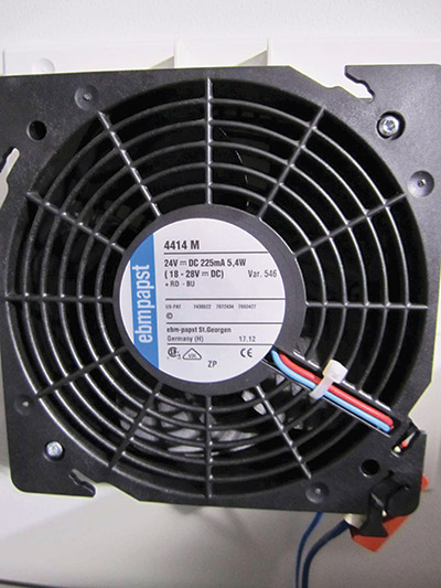
Photo 1. A motor marked with inherent overheating protection
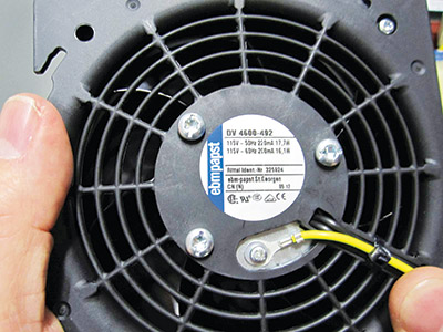
Photo 2. A motor that does not have inherent overheating protection
Other than the limited motors less than 1HP identified in CE Code Rule 28-308, motors not provided with inherent overheating protection will require remote overload protection. The setting of this overload protection is detailed in CE Code Rule 28-306. Motors with a service factor 1.15 and greater require the overload protection set at 125% of the motor full load ampacity and 115% for motors with a service factor less than 1.15. (See photo 3).
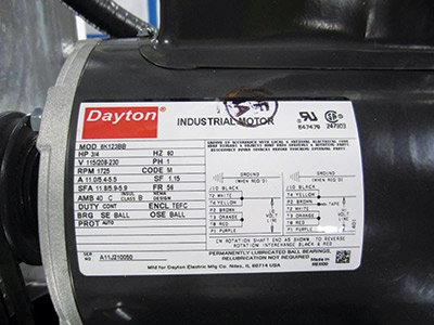
Photo 3. A motor nameplate where we can see the service factor (SF) of 1.15.
Remote overload protection can be provided by time delay fusing, overload relays, or other overload devices certified to CSA Standard C22.2 No 14 Industrial Control Equipment. (See photo 4).
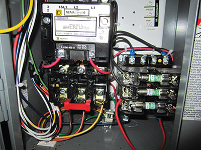
Photo 4. Motor overload relay for a motor that does not have inherent overheating protection
With the overload dealt with, we can now focus on the short circuit protection requirements. The traditional method to provide short circuit protection is by the installation of overcurrent devices such as fuses or circuit breakers with an ampacity rating based on CE Code Table 29. As an example, the short circuit protection (overcurrent protection) required for a synchronous motor is limited to 175% of the motor full load ampacity for time delay fuses, 300% for non-time delay fuses and 250% for circuit breakers. Such limitations are intended to allow the motor to start without operating the overcurrent device during normal operation of the motor.
In the uncommon event these ratings of protection do not allow the motor to start because the motor inrush current is too high, CE Code Rule 28-200(d) allows the overcurrent protection to be further increased to 225% of the motor full load ampacity for time delay fuses, and (400% for motor up to 100 FLA and 300% for greater than 100 FLA) for circuit breakers.
Another method to provide short circuit protection is by using self-protected combination motor controllers also known as Type E or Type F combination motor controllers. CSA Standard C22.2 No 14 defines these controllers as:
A combination motor controller having non-replaceable or integral discriminating overload and short circuit current sensors, and provided with one or more sets of contacts where the contacts cannot be isolated for separate testing, shall be considered a Type E. (See photos 5A and 5B).
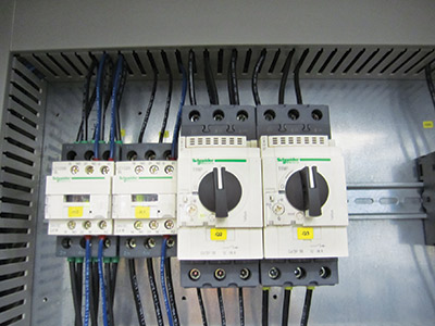
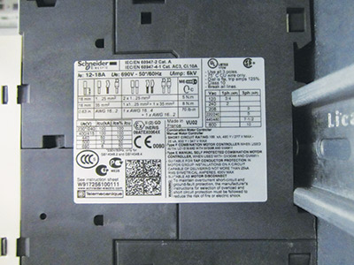
Photo 5A. Two Type E self-protected combination motor controllers. Photo 5B. The nameplate for one of the Type E self-protected combination motor controllers shown in Photo 5A. Note the accessories identified on the nameplate marking that must be installed before the controller can be accepted as a Type E self-protected combination motor controller.
A Type F combination motor controller is comprised of a magnetic or solid state motor controller coupled with a Type E controller. (See photos 6A and 6B)
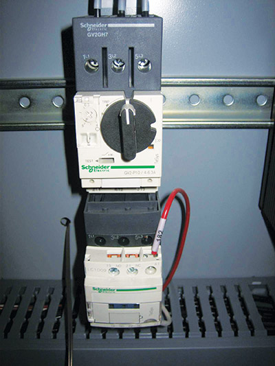
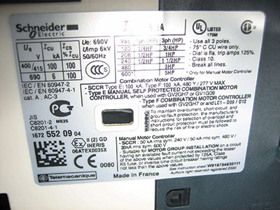
Photo 6A. A Type F combination motor controller. Photo 6B. The nameplate for Type F combination motor controllers is shown in Photo 6A. Note the accessories identified on the nameplate marking that must be installed before the controller can be accepted as a Type F combination motor controller.
Type E and Type F self-protected combination motor controllers provide a disconnection means, short-circuit protective device, motor controller, and overload protection.
Another method to install multiple motors on a single branch circuit is with a controller marked suitable for motor group installation in conjunction with a main branch circuit overcurrent device (fuse of circuit breaker). (See photo 7).
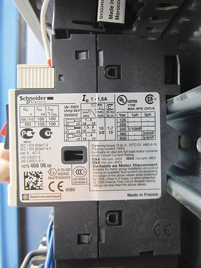
Photo 7. A motor controller marked suitable for motor group installation
Precautions must be considered when grouping motors on a single branch circuit. The first precaution to consider is the markings on the controller for such group installations. CSA Standard C22.2 No 14 requires the maximum overcurrent protection to be marked on the controller. (See photo 8).
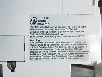
Photo 8. The maximum overcurrent protection that can be installed ahead of the group installation controller.
The second precaution to consider is the requirements of CE Code Rule 28-206. This rule directs code users to Rule 28-204 to limit the maximum overcurrent protection that can be installed ahead of the group installation controller.
For a feeder supplying motor branch circuits only, the ratings or settings of the feeder overcurrent device shall not exceed the calculated value of the overcurrent device permitted by Rule 28-200 for the motor that is permitted the highest rated overcurrent devices of any motor supplied by the feeder, plus the sum of the full load current ratings of all other motors that will be in operation at the same time.
As an example let’s look at a motor group installation consisting of five synchronous motors with full load ampacities (FLA) of 21, 2, 4, 7, 7, 7, and 16 A, and a main breaker installed ahead of the controllers marked suitable for group installation. (See table 1).

Table 1
CE Code Rule 28-206 limits the circuit breaker ahead of the group installation to a maximum of 93 A 21×2.5=52.5 = 50 Amp breaker + (2+4+7+7+7+16). Note: the marking on the controller for Motor 2 limits the main circuit breaker to 80 A. As a result, this example for is not code-compliant. One option is to replace the Motor 2 controller with a group installation controller marked for a maximum 125 A circuit breaker and ensure the main breaker is not larger than 125 A.
The third precaution is the size of the circuit conductors including the tap conductors. The tap conductors are the conductors installed between the group installation controllers and the motors. CE Code Rule 28-106(3) limits the size of the tap conductor to not less than 1/3 that of the larger branch circuit conductor for the group of motors.
The minimum allowed ampacity of the branch circuit conductors for the group of motors in this example is 69.25 A, 21×1.25 + (2+4+7+7+7+16). From the 75⁰C column of CE Code Table 2, a 4 AWG copper conductor with the ampacity of 85 A has been selected. The following table shows the tap conductor sizes and percentages of the larger conductor for our example. (See table 2).
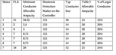
Table 2
As you see, the Motors 2 to 6 have 14 AWG copper conductors with an allowable ampacity of 20 A that is less than 1/3 of the larger 4 AWG copper conductor allowable ampacity of 85 A. This can be made code-compliant by installing 12 conductor in place of the 14 AWG copper conductors, or separating the largest motor from the group reducing the main circuit breaker and larger conductor size. The following table shows the revised group without Motor 1. This group would now have a maximum main circuit breaker of 70 A, 16×2.5 = 40 Amp breaker + (2+4+7+7+7) and a minimum conductor allowable ampacity of 47 A, 16×1.25 + (2+4+7+7+7). Resulting in a 8 AWG copper conductor as the larger conductor supplying the group installation controllers. (See table 3 ) .
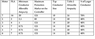
Table 3
The final precaution to consider is the length of the tap conductors. CE Code Rule 28-106(3) limits the length of the tap conductors to a maximum of 7.5 m. The following table shows our revised example detailing the tap conductor lengths proposed. (See table 4).
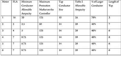
Table 4
As you can see the length of the tap conductor for Motor 4 is not code-compliant. If the conductor cannot be rerouted to limit the length of the tap conductor to 7.5m, individual overcurrent would need to be installed ahead of the tap for Motor 4.
Summary
The limitations when grouping motors on a single overcurrent device include the method of motor overload protection, short circuit protection for the motor branch circuit conductors, controllers and motors, size of the tap conductors, and the length of the tap conductors. The overload protection can be in the form of integral protection for the motor or remote overload protection as part of the control equipment. The maximum overcurrent device used to provide the short circuit protection for the motor branch circuit conductors, controllers, and motors must not exceed the limitations of Rule 28-206 and cannot exceed the maximum rating permitted by the rating marked on the group installation motor controller. The motor tap conductors must have an allowable ampacity not less than 125% of the motor full load ampacity. The motor tap conductor allowable ampacity must also be greater than 1/3 that of the larger conductor installed ahead of the group installation motor controller, and the maximum length of the motor tap conductor cannot exceed 7.5m.