
As PV systems become increasingly safer, NFPA has targeted firefighter safety in the 2014 NEC for PV systems. In addition to several requirements included in the 2011 NEC for firefighter safety — [690.4(F), which provided specific PV conductor installation requirements; 690.11, which provides a requirement for dc arc-fault protection; and 690.31(E), which provides further installation and marking requirements for PV conductors in a building]— NFPA established a task group in Code-Making Panel 4 (CMP-4) to address potential proposals for the 2014 NEC. The primary outcome of the firefighter safety task group was the development of a new code section 690.12 entitled “Rapid Shutdown of PV Systems on Buildings.” The focus of this new section is to allow first responders to quickly and easily control the PV system circuits leaving an array in a PV system. Although the most predominant issue of concern was “rooftop systems,” the requirement would also extend to ground-mounted systems if the conductors enter a building for more than 5 feet. Multiple methods to achieve rapid shutdown were discussed at length during the proposal and comment periods, resulting in the language that is currently in the 2014 NEC.
As with any new code language, it is helpful to understand what the committee was attempting to accomplish with the language so that those involved in either the installation of PV systems or the electrical code enforcement for the installation can appropriately understand and apply the electrical code requirements to the unique system installation. This article is intended to explain the language of the new section 690.12 and provide context and examples of how to understand and enforce the requirements. The examples that are portrayed in this article are not intended to be an exhaustive treatment of how to comply with 690.12, but rather are intended to show that there are numerous ways, with existing PV products, to meet the requirements of 690.12 and improve safety for emergency responders.
Background
Emergency responders are becoming more aware of the presence of PV systems as well as some of their inherent safety hazards. This awareness is particularly true in areas of the country where PV systems are common such as California, New Jersey, Hawaii, Massachusetts, just to name a few. One of the first questions a firefighter or other emergency responder asks is, “How do I shut the system down so I won’t get shocked?” This simple question may have a complicated answer for many PV systems. Thinking that a PV system is similar to utility electrical services, many fire departments have required a rooftop disconnecting means so that firefighters can turn off a PV system switch during rooftop operations believing that once they open the disconnect their concerns are alleviated.
While requiring a rooftop disconnect seems like a simple and logical approach to shut off a PV system, opening a disconnect switch does little, if anything, to reduce shock hazard on many PV systems. In fact, it can be easily argued that opening a disconnect switch provides a false sense of security to the emergency responder which may increase their likelihood of an electrical shock. The reason the danger still exists in many PV systems after opening a rooftop disconnect switch is that there are typically power sources on both sides of the switch. On the PV array side of the switch, the conductors are generally energized during daylight hours—typically at voltages of 300 volts dc or more. On the other side of the switch, often connected to an inverter with large input capacitors, the capacitors and parallel PV array circuits can keep that part of the circuit energized long after the switch is opened. This is why the NEC has required a warning sign on switches in PV arrays in 690.17, “WARNING: ELECTRIC SHOCK HAZARD. DO NOT TOUCH TERMINALS. TERMINALS ON BOTH THE LINE AND LOAD SIDES MAY BE ENERGIZED IN THE OPEN POSITION.” While disconnect switches serve an important function in the process of shutting down and isolating a PV array, they generally only stop the flow of current and therefore can’t be viewed as providing voltage isolation like they are in utility supplied AC systems.
The Need for Rapid Shutdown
Whether or not the fire service or other emergency responders understand the false sense of security a rooftop disconnect switch can provide, numerous fire departments have been requiring these switches. This is part of the reason that NFPA decided it was time to establish a task group and develop proposals to address the issue comprehensively. To that end, a shutdown requirement was developed to improve safety for firefighters, and this grew to cover all emergency responders. The new section 690.12 is entitled, “Rapid Shutdown of PV Systems on Buildings.” This new section includes details on which circuits require shutdown, the maximum allowable voltage on circuits that are shutdown, the timeframe required to accomplish the shutdown once the function is initiated, and how the initiating device is to be marked.
The primary objectives of 690.12, as written, are the following:
To quickly shutdown (10 seconds) PV system conductors
- inside a building and more than 5 feet long
- outside a building and more than 10 feet from the PV array
Allow no more than 30 volts on shutdown conductors (generally considered touch-safe in a wet environment)
Provide simple marking, where most beneficial to the firefighter, informing how to perform shutdown
Use listed equipment to perform the shutdown
Since the NEC is an installation requirement and not an instruction manual, the details of how to accomplish the requirements in a PV system installation are open to interpretation. This has become a part of the problem for jurisdictions that have already adopted the 2014 NEC and CMP-4 will need to address some of this openness for the 2017 NEC. This article will provide some background on meaning and compliance options for 690.12 in hopes that this information may be of some assistance for those attempting to apply the 2014 requirements.
So what exactly does Section 690.12 require?
“690.12 Rapid Shutdown of PV Systems on Buildings. PV system circuits installed on or in buildings shall include a rapid shutdown function that controls specific conductors in accordance with 690.12(1) through (5) as follows.
“(1) Requirements for controlled conductors shall apply only to PV system conductors of more than 1.5 m (5 ft) in length inside a building, or more than 3 m (10 ft) from a PV array.
“(2) Controlled conductors shall be limited to not more than 30 volts and 240 volt-amperes within 10 seconds of rapid shutdown initiation.
“(3) Voltage and power shall be measured between any two conductors and between any conductor and ground.
“(4) The rapid shutdown initiation methods shall be labeled in accordance with 690.56(C).
“(5) Equipment that performs the rapid shutdown shall be listed and identified.”
Which PV systems must comply?
Rapid shutdown, as stated in 690.12, is for PV system circuits in or on buildings. This means that a PV system where all the equipment and conductors are not mounted on buildings are not required to follow 690.12. However, other situations may exist where 690.12 should be applied. One example is a ground-mounted system where the PV system circuit conductors are run along the outside or into the building, for instance to an inverter in a utility room. In this case, the conductors on or entering the building would be required to follow 690.12. Clearly, any PV system mounted on a building, whether or not the conductors enter the building, must comply with 690.12.
What conductors must be controlled?
In general, PV system conductors include all current-carrying conductors related to a PV system, both dc and ac. The best way to describe these conductors is with examples of typical PV system types.
PV system conductors more than 5′ in length inside a building
PV system conductors inside a building include conductors entering an attic space from the roof or conductors connected to an inverter inside the building. Battery-based PV systems, which are discussed in examples in this section, can present difficulties in complying with 690.12 since these systems are expected to operate during power outages.
Utility-interactive, no battery storage
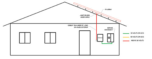
The first PV system type to discuss is a utility-interactive PV system with no battery storage. This is by far the most common type of PV system that an AHJ will encounter. For this example, the PV array is on the roof of a single-family home and the inverter is in the garage. PV source circuits are run in metal conduit from the roof, through the attic [690.31(G) 2014 NEC] and into the garage to connect to the inverter. To hide the conduit, the penetration through the roof and into the attic is done under the PV modules. Inside the attic, the circuits must have a remotely activated switch of some kind within 5′ of entering the attic. Of course, the remotely activated disconnect could also be outside the attic and closer to the array if that is more practical. On the other end of the circuit, unless the inverter can internally reduce the voltage to no more than 30 volts or isolate the capacitors in 10 seconds, another shutdown switch is required within 5′ of the inverter. The dc switch at the inverter is shown as a remotely operated switch in figure 1.
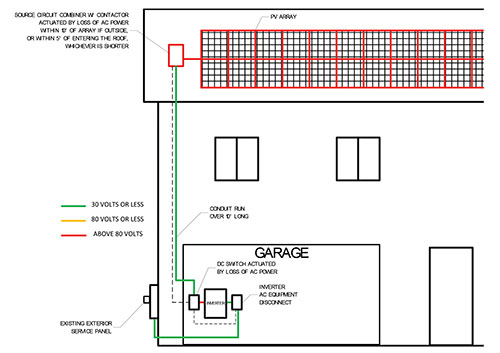
If the dc disconnecting means were used as the rapid shutdown initiator, this switch would also have to activate the switch in the attic and should be grouped with the service disconnecting means so that a firefighter can easily turn off utility power and the rapid shutdown from the same location. If both the attic switch and the dc switch at the inverter are remotely activated upon loss of ac power, then the service disconnecting means could be the rapid shutdown initiator for the PV system. If the PV system is connected on the line side of the service disconnecting means, and both the attic switch and the dc switch at the inverter are remotely activated upon loss of ac power, then the ac PV system disconnecting means, adjacent to the service disconnecting means, could be used as the rapid shutdown initiator. This illustrates why a specific type of rapid shutdown initiation device is not defined in the NEC.
Utility-interactive with battery storage
The introduction of battery storage adds a layer of complexity to the rapid shutdown process. Most battery storage systems are designed to power select loads during a utility power outage. Since standby power is the primary reason for the battery, actuating rapid shutdown on loss of utility power defeats the purpose of the equipment. Therefore, these battery-based systems need to have a rapid shutdown initiator that is independent of utility ac power shutdown. This independent shutdown initiator could be a simple control switch, such as a red pushbutton OFF switch, that controls remotely actuated switches. Where the switches must be located is a function of the PV array design and the standby power system design. If the inverter and battery are in the garage, and the array is on the roof of a single-family dwelling as in the first example, then remotely activated switches would be required in the same locations as the first example if the conductors are run through the attic to the garage (see figure 2). However, this is not the end of the shutdown requirement since the inverter is also fed by a battery. If the battery cables are less than 5′ in length from the battery to the inverter, no remotely actuated switch is required on the battery cables. If there is no battery circuit shutdown because of the short battery cables, then a remotely activated ac switch would be required on the stand-alone ac inverter output circuit (see figure 2).
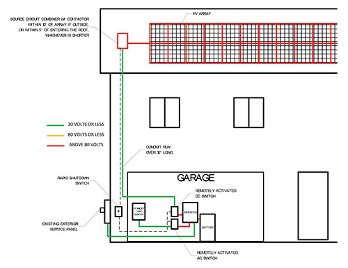
If the inverter is more than 5′ from the batteries, this battery circuit must also comply with 690.71(H) and a remotely activated switch within 5′ of the battery could be used to comply with both 690.12 and 690.71(H). In this case, a remotely activated ac switch would not be required on the stand-alone ac inverter output circuit since the inverter will automatically shut down all ac output power upon loss of all dc input power (battery and PV). Just as with utility-interactive PV systems without battery storage, the ac circuit between the utility service and the inverter automatically shuts down upon loss of utility power.
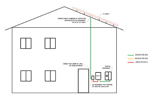
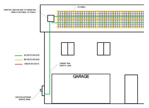
Conductors on and outside the building more than 10′ from a PV array
For the conductors in a PV system that are kept on the outside of a building, 690.12(1) requires that the conductors be controlled within 10′ of the PV array. This 10′ allowance is to provide ample conductor length to make a connection to a remotely activated switch. For example, consider an inverter on the outside of the building as shown in figure 3. The inverter is mounted more than 10′ from the array, so a remotely activated switch is required within 10′ of the array. To activate the rapid shutdown upon loss of utility power, a remotely activated switch would be required on the dc side of the inverter to isolate the capacitors in the inverter from the PV output circuit. As stated in the first example, this function may also be provided internal to the inverter equipment. If the inverter is located adjacent to the service entrance, the dc disconnecting means at the inverter could provide the rapid shutdown initiation provided that the dc switch also activates the switch near the PV array (see figure 3).
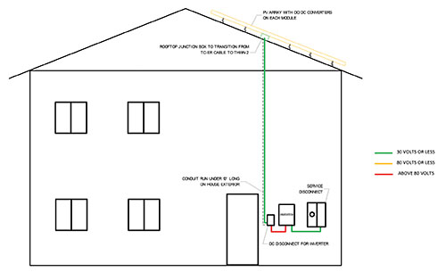
A similar example to the one shown in figure 3 could be accomplished with dc-to-dc converters at the PV modules. Similar to micro-inverters, these converters can shut off the power from the modules remotely. Different from micro-inverters, yet similar to string inverters, the dc input circuit to the inverter needs to be isolated for rapid shutdown. Figure 4 shows a dc-to-dc converter installation where the dc disconnect on the inverter isolates the inverter and shuts down the dc-to-dc converters.
Another case would be where the string inverter is mounted within 10′ of the PV array as shown in figure 5. This string inverter PV system would not require any remote switches to comply with 690.12.
Why 30 volts?
Many methods used to control conductors will actually de-energize the conductors completely to zero volts. However, because of the use of capacitors in PV inverters and control conductors used for operating contactors (often 24 volts), these circuits may have some residual voltage if switches are not used. The focus of 690.12 is on the shock hazard level which is defined in various national and international safety standards as voltages above 30 volts in a wet environment.
What are some currently available methods for compliance?
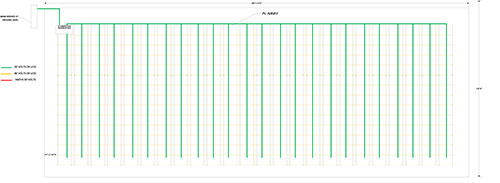
The previous examples showed several methods of compliance for what are commonly called string inverters used in residential PV systems with and without battery storage. There are several other currently available methods that can be equally compliant with 690.12. One common PV system design method is installing micro-inverters on every PV module. By putting an inverter on every module, whether separately or as part of a listed assembly (ac module), the PV system will be shut down upon loss of utility power without additional remotely activated switches. For load-side connected PV systems, the service disconnecting means can be the rapid shutdown initiator. For supply-side connected PV systems, the PV system disconnecting means, adjacent to the service disconnecting means, can be the rapid shutdown initiator. This method of compliance can be used for the smallest PV systems (see figure 6) up to large megawatt-size PV systems on commercial rooftops (see figure 7). The reason that the utility-interactive side of the inverter output circuit is considered compliant with 690.12 is that all PV inverters that are listed as utility-interactive cease energizing this circuit upon loss of utility power [690.61]. This shutdown feature is incorporated into all utility-interactive inverters, regardless of size.
Large commercial rooftop PV systems
In addition to the micro-inverter method of compliance described above, there are several products available for commercial rooftop systems to comply with 690.12.
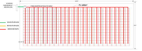
String inverters on large commercial rooftops
Currently, one of the most common methods of PV system design for large commercial rooftop systems uses 1000Vdc string inverters, each outputting 15–50 kW. Rather than using a large central inverter with 5–20 source circuit dc combiners on the roof, this recent method typically consists of 3–10, 1000Vdc source circuits to the inverter that outputs at 480Vac, three-phase power to the building. By placing these smaller inverters within 10′ of the array that they are connected to, the PV system can meet the requirements of 690.12 and shutdown can be initiated upon loss of utility power without any remotely activated switches (see figure 8). The additional benefits of these smaller inverters is that they generally have far better ground-fault detection than larger inverters sold today and also incorporate arc-fault detection inside the inverter. Most large central inverters must have arc-fault detection added externally in the PV system since the large inverters generally do not have arc-fault detection internal to the unit (though they do have ground-fault detection).
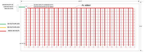
Central inverter at ground level with contactor dc combiners on rooftop
For large central inverters used with rooftop PV arrays, rapid shutdown requires the use of remotely actuated switches on the roof, typically one switch at each of the 5–20 source circuit dc combiners. Some large central inverters have dc input contactors that will open and isolate their input capacitors within 10 seconds of loss of dc power or loss of ac power. For those inverters that do not have dc input contactors, remotely actuated switch(es) need to be installed to isolate in the input capacitors for rapid shutdown (see figure 9). The most commonly used remotely actuated switches in PV systems today are contactors that operate from a 24V power supply. These normally-open contactors require 24V power to stay closed. To remotely open these contactors, all that is necessary is to interrupt the 24V power. These contactors are typically part of listed source circuit dc combiners that are available from several different manufacturers.
If the inverter does not have an internal contactor to separate the input capacitors, PV output circuit combiners, typically installed adjacent to the inverter, are available with the very same normally open contactors. If the 24V power supply receives its power from the service disconnecting means or the ac PV system disconnecting means, and the switch that supplies power to the 24V power supply is labeled as the rapid shutdown initiator, then the PV system is compliant with 690.12.
New products developed specifically for 690.12
This article has discussed products that are currently available and meet the requirements of 690.12 including the listing requirement 690.12(5). 690.12(5) does not require that the listed products be specifically listed for rapid shutdown so that “off the shelf” products such as contactors, motorized switches, and shunt-trip breakers, used in accordance with their listings can be used to comply with 690.12. As test standards are developed for rapid shutdown of PV systems, more options for compliance will be available. For instance, there is a specific reason 10 seconds was chosen as the time frame to achieve 30 volts on a controlled circuit. This was to allow inverter manufacturers to change their designs to de-energize their input capacitors using innovative features, other than contactors. Most inverters take 3–5 minutes for the bleed resistors on their input capacitors to drain off the voltage. Methods other than typical bleed resistors would be required to dissipate capacitors in 10 seconds. As standards are developed to test equipment that is specifically designed for rapid shutdown, devices other than switches and contactors will become available.
Conclusion
The requirements of 690.12 in the 2014 NEC represent a substantial change, and a step forward, in the safety of PV systems. Design methods and products currently exist that meet the requirements of 690.12. Understanding which conductors must be controlled, and the currently available products that can meet the control requirements, will help PV system installations comply with 690.12. Code enforcement officials must also understand the meaning of 690.12 so that compliant systems can be approved. As with all new NEC requirements, it takes time for the various involved stakeholders to become educated on how to design, install and enforce these new requirements for rapid shutdown. It is hoped that this article will help provide some of this necessary education.
If images are too blurry for your screen, download a PDF copy of this article