In the last few years, advancements in control technology and energy management have made compliance with National Electrical Code, Article 700, Emergency Systems, more complex, with far more design choices available to the specifier or installer. In the March/April 2011 issue of IAEI News the requirements and practices of the time were reviewed and several examples were explained in our article “Understanding Control of Emergency Lighting Circuits.” Continuing upgrades to the NEC and UL standards as well as advances in equipment are now explained in this update.
NEC section 700.1 and the definition of emergency systems in section 700.2 make it clear that emergency systems are to automatically provide power and illumination. While it is possible to provide power and not actually use it for some emergency purpose, the word “illumination” dictates that light must automatically be provided. Consequently, any switching or control in lighting circuits must be automatically forced on in order to comply.
Switching Equipment
One method of accomplishing the above requirements is by using an automatic emergency transfer switch (AETS) to connect the lighting circuits to normal or emergency power. Applying AETS devices to feeders is a common occurrence since typical AETS devices are high-current three or four-pole devices. Historically, AETS devices have also been applied to branch circuits, especially when loads were driven from a dimmer system. But when this type of design has been scaled down and applied to branch circuit applications, the result has often been expensive and over-designed. However, such branch circuit applications of scaled-down large emergency transfer switches were the norm for many years, primarily driven by the requirement of NEC 700.5(C) for all emergency transfer switches to be electrically operated and mechanically held (EOMH).
Despite the mechanically-held requirement of 700.5(C), a class of low-cost transfer-capable devices for use on branch circuits began to appear in the early 2000s. These devices were typically listed as automatic load control relays (ALCR) under UL 924 or as automatic transfer switches suitable for use under Article 702, but not Article 700. They were non-compliant with 700.5(C) and had not undergone any evaluation as transfer switches for endurance, fault current, and other tests required by the UL 1008 standard for Emergency Transfer Switch Equipment. This situation led to changes in both the NEC and the UL 1008 standard.
First, in the 2011 NEC, automatic load control relays were defined in section 700.2, and section 700.24 was added to specify the requirements of ACLRs. Among those requirements was the statement “The load control relay shall not be used as transfer equipment” which also reflects language in UL 924. Second, UL convened a task group to bring transfer-capable ALCRs that were potentially suitable for use under Article 700 into the UL 1008 standard. The result was a revision to the standard that created a new device: the branch circuit emergency lighting transfer switch (BCELTS). These devices are transfer switches for use on emergency lighting branch circuits rated not over 20 A. While they have no mechanically-held requirement, they are required to undergo all the endurance, fault current, and source interconnection prevention tests of an emergency transfer switch. Third, in the 2017 NEC, BCELTS devices were defined in section 700.2, and section 700.25 has been added detailing the requirements of the BCELTS, specifically removing the mechanically-held requirement of 700.5(C) for these devices.
The result is that there are now two distinct types of branch-circuit devices identified in NEC Article 700, automatic load control relays (ALCR) and branch circuit emergency lighting transfer switches (BCELTS).
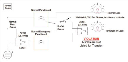
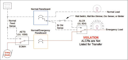
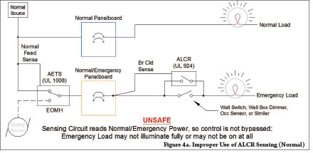
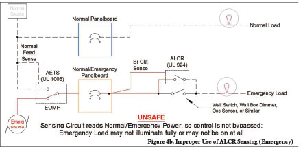
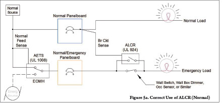
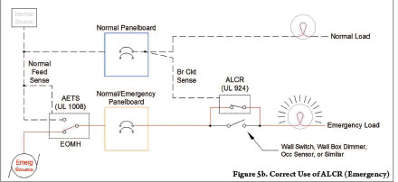
ALCRs are covered by 700.26 in the 2017 edition of the NEC and Listed to UL 924, Emergency Lighting and Power Equipment, under Category FTBR. Whether or not they appear to have transfer functionality, they are suitable only to bypass switches or control equipment fed from a single normal/emergency source, not to transfer between normal only and normal/emergency sources. The normal/emergency source must be provided via an upstream emergency transfer switch. See figures 3, 4, and 5.
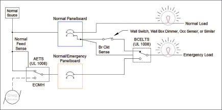
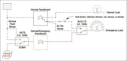
BCELTS devices are covered by 700.25 and listed to UL 1008 under category WPWR. They are suitable for transferring emergency lighting loads from one source to another on branch circuits rated not over 20 A, but are not required to be mechanically held. See figures 1 and 2.
Equipment with Integral Bypass Function
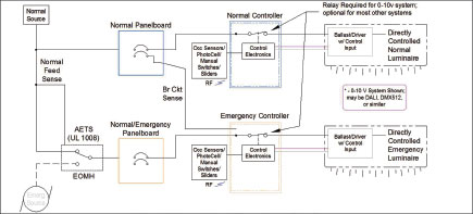
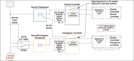
The bypass switching equipment described above is usually wired in conjunction with a lighting control device. Many lighting control manufacturers are now integrating the bypass function by obtaining an additional UL 924 Listing under FTBR on their control equipment for emergency use. Often these control devices may be used on normal lighting circuits, and by applying a provided “emergency” label and proper wiring, also on emergency circuits. This integrated emergency function appears in dimmer/relay panels, control panels, switchbox devices and control modules mounted above ceilings. Included are network controllers that drive 0-10 V and DALI ballasts, and LED drivers. The UL 924 Listing assures that there is some sort of emergency input, that when asserted, energizes the circuit, and that no other control signals can de-energize the circuit until the emergency input is de-asserted. See figure 6.
Directly Controlled Luminaires
Some luminaires, previously controlled by dimmer or relay panels, contain integral dimming or switching controlled by an external signal. These luminaires are now defined in section 700.2, and 700.24 contains the requirements regarding emergency systems using directly-controlled luminaires. There are three basic types of these luminaires all of which must be fed from an emergency source and listed for use in emergency systems.
1) Luminaires where the absence of control commands causes the luminaire to illuminate,
2) Luminaires where the control commands and the emergency commands are provided by separate control systems, or
3) Luminaires where the control commands and the emergency commands are on the same control input.
The first type is the one most familiar. The luminaire contains a dimming ballast or LED driver controlled with a 0-10 V analog signal or a DALI digital signal. The 0-10 V control signal is held high by the ballast/driver, and the controller pulls it low to dim or turn the luminaire off. The result is that opening the control line causes the luminaire to illuminate. DALI functions similarly, in that opening the control line in the default programmed mode causes the luminaire to illuminate (this setting can be field programmed for other behaviors). In some cases, in order to assure the luminaire can be turned fully off, a relay is placed in the AC input. In the emergency mode, the control contact must be opened and the power contact closed. The device that provides this function must be Listed to UL 924.
The second type has a device or circuit inserted in the control line. The device has a separate emergency input, usually to accept a switch closure or a hold-up voltage. When asserted, the control line is blocked, and the luminaire is forced to full. The device or circuit intercepting the control line must be listed to UL 924 and may need to be supplied from an emergency source.
The third type has a digital control line or lines that have special commands that cause the luminaire to illuminate. When the special command is asserted all other commands must be blocked until the special command is removed. The controller and its power supply must be listed to UL 924 and supplied from an emergency source. Since this type lends itself to controlling many luminaires and any fault will cause all luminaires to cease illumination, care must be exercised to assure there is a backup system and control wiring to assure that the required illumination is not removed in any area.
Return-to-Normal Behavior
The NEC requires automatic illumination when there is a failure of the normal source, but it is silent regarding what is required when the normal source returns. Most equipment will return to normal immediately upon the restoration of normal power, which may not always be desirable or safe. Deliberate manual input by qualified personnel may be necessary in order to safely return to normal lighting. Another condition that may require a controlled return to normal is that of inrush current. Tungsten lamps and electronic ballasts/drivers could draw huge inrush currents when they are all returned to normal immediately. These system-level behaviors must be analyzed for each and every emergency lighting system.
Other Considerations Involving Emergency Illumination
While not stated in NEC Article 700, normal supply failure and system accidents are not the only considerations requiring egress lighting. NFPA 101, Life Safety Code, requires minimum levels of illumination. Reduced levels in places like theatres must be raised to the required minimum if the emergency function is activated. Many fire codes require emergency systems to be activated upon receipt of a fire alarm. Spaces may need egress lighting in case of medical emergencies, and these days, terrorist attacks. These additional considerations cross over between emergency and optional standby systems depending on jurisdictions.
Conclusion
The above discussion is illustrated by a situation that actually occurred in a hotel with seven restaurants deep inside the building. All the lighting was controlled by a single analog dimmer panel, which had the required transfer equipment to remove the emergency lighting loads from the dimmer output and connect them to the emergency feeder upon sensing the failure of the normal feeder. Unfortunately, the power supply fuse to the controller failed, and all restaurants went dark. The transfer switches did not transfer because the normal feeder did not fail, the fuse did. This illustrates the importance of the concept covered in 700.16, which states in part:
“Emergency lighting systems shall be designed and installed so that the failure of any individual lighting element, such as the burning out of a lamp, cannot leave in total darkness any space that requires emergency illumination.”
Any compliant emergency system must satisfy that requirement, which likely requires a system-level review of the design and functionality of the solution by the AHJ. In addition, Article 700 covers the supply, distribution and control of electricity for illumination—the whole system. The entire path from the emergency source to the lighting load must be guaranteed to be full-on, either by transfer, bypass or control system state. This includes the switches, dimmers, occupancy sensors, photocells, energy management equipment and any control signal required to drive circuits to full. Listing of components to emergency standards cannot be relied on to insure proper system operation. All components in the system must be reliable, sufficiently powered and analyzed and tested to work properly as a system.