In the previous article in this series, we saw how the voltages from PV modules are affected by the environment and how the National Electrical Code (NEC) deals with these voltages. In this article, we will look at the dc currents in the PV system and see how they vary with the environment and how the Code is modified from the normal requirements to deal with these variations.
Sunlight Varies. This statement is not trivial as most would suppose. Yes, the sun does go down at night, and there is no irradiance on the PV modules during that time. All of the PV module parameters including maximum-power output (Wmp), maximum-power voltage (Vmp), and maximum-power current (Imp), as well as short-circuit current (Isc) are rated at the standard test conditions (STC) of 1000 watts per square meter (W/m2) of irradiance and a temperature of 25° C (77° F). Of interest at this point in our assessment of the PV system are the current parameters. The highest current that a module can produce is the short-circuit current and this current is typically 10 to 15% higher than the max power current, where the module normally operates.
The current that a PV module can produce is a very slight function of temperature, it increases slightly as temperature increases and is generally ignored except on the very large arrays. But, the current is a very strong function of sunlight or irradiance, and in fact, both the short-circuit current and the maximum-power current are a direct function of the irradiance on the PV module. While the value of 1000 W/m2 is used for the STC value of irradiance, the actual irradiance on a PV module can be significantly higher. In most locations, the irradiance will peak at solar noon given clear skies with no obstacles obstructing sunlight on the module. This irradiance peak may approach 1250 W/m2 , and I have measured 1197 W/m2 for a period of three hours in the sunny Southwest. Since the condition of the air in terms of humidity, dust, smoke, pollen and other local climatic conditions will affect the amount of sunlight hitting the module, peak irradiance will vary throughout the country and seasonally. Due to the less dense air mass, PV modules installed at higher altitudes will receive increasing amounts of irradiance as the altitude increases.
Transient Conditions Not Considered. Snow, clouds, sand, and water may create reflective surfaces that increase the irradiance on the PV modules by a significant amount: sometimes as much as 1500 W/m2. As the clouds move and the earth turns, the sun angle with respect to the reflecting surface and the modules will change causing these conditions to be transient, usually lasting only a few minutes. They are not continuous, and the currents that they generate are not considered in Code calculations.
Although the currents in a PV system vary from zero during the night to a peak at solar noon on clear sunny days, PV system currents in the dc circuits and the ac output circuits of utility interactive inverters are considered to be continuous and at their maximums at all times. The reason for this is that during the daytime, when the air is clear, and there are no obstructions, the irradiance can be more than 1000 W/m2 for a period of three hours or more in many locations in the country. In the PV system, as now defined in the 2017 NEC [figures 690.1(b), 690.2], there are no noncontinuous currents. Energy storage systems (ESS) addressed in Article 706 will have different currents, as will standalone PV systems in Article 710.
Adapting the Code to PV Currents. When the irradiance is greater than the STC value, we get a PV system that can produce more power (voltage and current) than its rated values at STC. The NEC acknowledges this situation and has requirements for using the STC rated current that address it. Since the short-circuit current is the highest current the PV module can produce (for any given value of irradiance), an adjustment is made to the rated short-circuit current of the PV module (at STC) before that current is used in calculations for ampacities and overcurrent devices. A factor of 125% is used to adjust the rated short-circuit current to a value that includes the safety factor necessary to deal with increased dc current output from the PV module when the irradiance exceeds 1000 W/m2 . This factor is very clearly defined in section 690.8(A)(1)(1) of the Code, and the new current is called the maximum current and is used for subsequent calculations of conductor ampacity and overcurrent device ratings.
100kW and Up. For PV systems with a generating capacity of 100 kW or more, a professional engineer may calculate the maximum current based on PV array simulations using the maximum available 3-hour irradiance at the installation location and the array orientation. This calculation shall result in a maximum current of not less than 70% of the current calculated from the 125% Isc value which is not less than 87.5% of the Isc rating at STC [690.8(A)(1)(2)]. This allowance adjusts the array current output and, subsequently, the conductor sizes for real-world conditions.
As noted in the previous article, voltages of PV modules add when the modules are connected in series, however, the current stays the same for a series connection of modules at the value of the single module. Modules or strings of modules connected in parallel have the maximum current of each module or string of modules added to the maximum current of the other modules on strings of modules. That is why 690.8(A)(1)(1) requires that the 125% factor be applied to the sum of any parallel connection of modules. Of course, the 125% could be applied to the maximum current of individual strings of modules and the sum taken after the strings are paralleled. The paralleled output of two or more strings of PV modules is considered a PV output circuit [690.2, 690.8(A)(2)].
Continuous and Noncontinuous Currents
Throughout the Code, when dealing with currents, we see the phrase “125% of the continuous currents plus 100% of the noncontinuous currents” [e.g. 210.19(A)(1), 215.1(A)(1)]. This Code requirement is used when calculating the ampacity of conductors and to some extent in the rating of overcurrent devices. There is an exception to that 125% factor. When the circuit is protected by an overcurrent device in an assembly that is rated as an assembly for 100% operation, then the cable may have a starting ampacity calculation of 100% of the maximum current, but these assemblies are very rare indeed, especially in dc PV circuits. The math is relatively simple. The reciprocal of 1.25 is 0.8. In most cases, we can take the maximum current and multiply it by 1.25 and select an ampacity (given other considerations below) or start with a conductor ampacity and multiply by 0.8 to determine the continuous current capabilities of a particular conductor.
Since the maximum current for PV system is considered continuous, a second 125% factor may be applied to the short circuit current in many cases when conductor ampacity and overcurrent device ratings are being calculated. Although the factor is numerically identical to the 125% associated with the safety factor for irradiance over 1000 W/m2 , it a separate and distinct factor. Some calculations multiply the two factors together and get a combined factor of 1.56 (1.25 x 1.25 = 1.56), however, this is becoming less common since the Code ampacity calculations have been clarified as noted below.
PV DC Circuit Ampacity Calculations
The NEC requirements for calculating conductor ampacities are designed to ensure that the conductors do not operate over 80% of their rating continuously or if there are significant conditions of use involved, the conductor size is determined by those conditions of use. In past editions of the Code, the ampacity calculations were not clearly defined to indicate that only one of these two requirements applied. In the 2011 through 2017 editions of the NEC, the calculations have been made more transparent. Conductor ampacity shall be determined by one of two separate calculations, but both are not used in succession.
The Greater Of. Two separate calculations are made for conductor ampacity and the largest cable size resulting from those separate calculations is used. First, cable size (ampacity) is determined by taking 125% of the maximum current in the circuit. This calculation results in a current which is used in the appropriate conductor ampacity table to determine a cable size for the type of cable being used [690.8(B)(1)]. Note that no conditions of use are involved in this calculation or cable selection.
For example: The maximum current is 20 amps. Six (6) USE-2 conductors are in conduit and the ambient temperature is 50°C and there is no exposure to direct sunlight.
First calculation:
Maximum current = 20 amps.
1.25 x 20 = 25 amps
With USE-2 conductors in conduit, a 14 AWG conductor is determined from the ampacity table [310.15(B)(16)].
A second calculation takes the conditions of use factors when all have been multiplied together and divides this combined conditions of use factor into the maximum current to determine a new current (ampacity) and that value will be used in the appropriate ampacity table to select a cable size [690.8(B)(2)]. The larger cable of the two calculations is used. Note that the 125% factor is not used in this determination.
Second calculation: The maximum current = 20 amps. Six conductors are in a conduit at an ambient temperature of 50°C. There is no sunlight exposure.
Conduit fill factor = 0.8 [Table 310.15(B)(3)(a)]
Ambient temperature factor = 0.82 [Table 310.15(B)(2)(a)]
Combined conditions of use = 0.8 x 0.82 = 0.656.
Maximum current divided by conditions of use = 20/0.656 = 30.48 amps.
A 10 AWG conductor is determined from the ampacity table [310.15(B)(16)] and this conductor is the larger of the two conductors resulting from the two separate calculations.
For those mathematically inclined, it is interesting to note that since we are multiplying by 1.25 in one calculation and dividing by the combined conditions of use factor in the second calculation, a combined condition of use of 0.8 will yield the same cable size as the 125% calculation. Therefore, if the combined conditions of use are smaller than 0.8, the conditions of use equation will determine the conductor size. A combined conditions of use factor of greater than 0.8 indicates that the 125% factor will dominate.
PV modules have attached cables that are typically made of PV wire and are sized large enough to deal with all expected conditions of use that they may be exposed to. They are typically single conductors mounted in free air. It should be noted, however, that the field-installed conductors from strings of modules may have to be larger than the module conductors because there may be a number of these conductors in conduit with sunlight adders and conduit fill conditions.
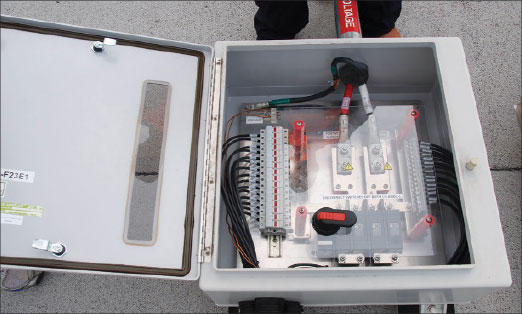
Paralleling Strings of Modules. Typically, multiple strings of modules are paralleled in a dc combiner or at the input of a utility interactive inverter which has an internal dc combiner (photo 1). These dc combiners will have fuses (or circuit breakers) for each of the inputs and these overcurrent protective devices protect the string conductors and the modules from overcurrents from sources external to that particular string. When making the parallel connections without a fused (or circuit breaker) combiner, it is important to ensure that all conductors are protected from overcurrents from all sources. These overcurrents may come from parallel connected strings or from external sources like inverters or charge controllers that are external to or downstream from the parallel connection.
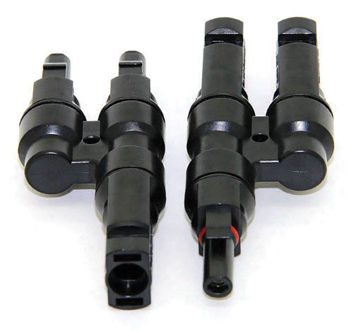
A Warning. It is becoming more common to have to strings of modules combined with a Y type cable adapter which may or may not have fuses inside the adapter or connected to the adapter for each input string (photo 2). Without fuses, the issue is what are any potential external currents from downstream further combinations of strings of modules or from backfeed from the utility through the inverter into a fault in the array wiring? These are the sources of external overcurrents that have to be addressed before this type of unfused paralleling can take place (690.9 Exception). In many cases it is difficult to obtain information on whether or not the inverter can backfeed currents into faults in the dc PV array wiring. These adapters are made by numerous manufacturers and, of course, the manufacturer of the Y adapter must be the same manufacturer who makes the connectors used on the PV modules and the connector used on the output cable from the Y adapter to ensure the listing on all connectors and the modules remains intact; all MC-4 type connectors are not equal.
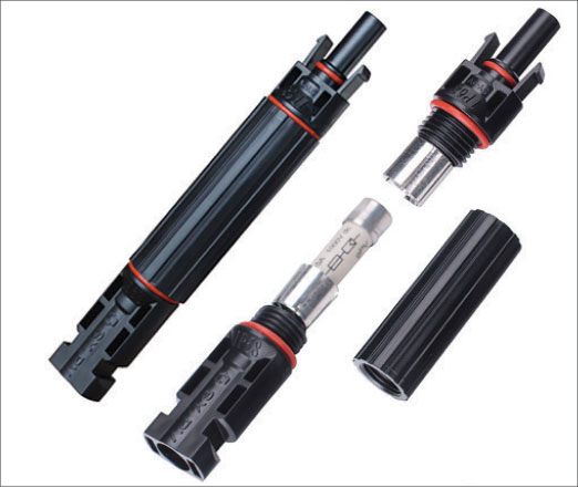
In situations where the Y adapter has fuses for both inputs internal to the adapter or where inline cable fuses are used on each input, the environment that the fuses operate in must be considered (photo 3). Fuses listed for PV applications are listed with a maximum operating temperature of 50° C. It is probable on a typical rooftop application that the adapter and fuses will be in an ambient temperature (around the cable/adapter) environment of 40° to 50° C and be subject to solar heating from direct exposure to sunlight. Although the 2017 NEC has deleted any sunlight adders on temperature for cables that are more than 7/8 of an inch above the surface [310.15(B)(3)(c)], it seems evident that conductors anywhere within that 2014 NEC space of 36 inches will be subjected to additional solar heating. In a recent PV installation, my tools on an open stand about 12 inches above the roof in the sun became far too hot to handle without gloves in just a few minutes. It is likely that the fuses in these Y adapters will frequently be subjected to more than 50° C even when they are behind the PV modules on a rooftop installation. This will mean the fuses are operating outside of the listed environment and the listing is invalid which is a violation of the Code. I urge caution any time these Y adapters with or without fuses are being used in a PV application.
Cable types. With the 2017 NEC, exposed cables used to connect modules and strings of modules in a PV array are now allowed to be USE-2 or PV wire on either grounded, functional grounded or ungrounded PV arrays. PV wire has an outside diameter that is not standardized and cannot be compared with other types of conductor insulation. There is no table for conduit fill in Annex C of the Code and the conduit fill must be calculated using Table 1 in Chapter 9 and the specifications for the PV wire being used.
Although PV wire is available in multiple colors and all PV wire is marked Sunlight Resistant, there are some data that indicate that colored insulations may not be a durable in the PV application as the basic black insulated conductors. This is due to the lack of carbon black in the colored insulations. USE-2 in black, while not marked Sunlight Resistant, has more than a 35-year history of exposure in PV systems in the hot, sunny Southwest.
In the next article, overcurrent protection will be covered.
Summary
The dc currents produced by PV modules vary directly with sunlight intensity and when the irradiance exceeds 1000 W/m2 , the currents may exceed the Standard Test Conditions (STC) rated values of Imp and Isc. The maximum current a module can deliver is Isc and the rated Isc is multiplied by a safety factor of 125% to deal with varying output currents above the standard rating and to yield a calculated maximum current to be used in subsequent ampacity and overcurrent device calculations. All PV currents are considered continuous and have been frequently measured above the STC values for three hours or more. The ampacity of the dc conductors is determined by the greater of a second 125% multiplier on the maximum current or the maximum current adjusted for the conditions of use, whichever yields the larger conductor.
For More Information
The author has retired from the Southwest Technology Development Institute at New Mexico State University but is devoting about 25% of his time to PV activities to keep involved in writing these “Perspectives on PV’ articles in the IAEI News and to stay active in the NEC and UL Standards development process. Seven- to eight-hour presentations are still available on PV and the Code, and they cover 2011–2017 NEC requirements. He can be reached at e-mail: jwiles@nmsu.edu, phone: 575-646-6105
The Southwest Technology Development Institute web site maintains a PV Systems Inspector/Installer Checklist and all copies of the previous “Perspectives on PV” articles for easy downloading. A color copy of the latest version (1.93) of the 150-page, Photovoltaic Power Systems and the 2005 National Electrical Code: Suggested Practices, written by the author, may be downloaded from this web site: https://swtdi.nmsu.edu/codes-standards/