‘Twas a dark and stormy night. The rain was pouring down, the wind was swirling around the house, and thunder and lightning were much in evidence. Kate was not getting much sleep. The dog and cat were terrified from the lightning flashes and the thunder crashes. The dog ended up in the bedroom closet, and the cat hid under the bed trying to escape the onslaught of light and sound. With thunder following the lightning strike by less than 15 seconds, Kate knew that the strikes were within three miles. The rain was much welcome due to the dry conditions that had existed for months. However, the lightning was a potential threat in their wildland urban interface (WUI) community. But the community and her house had been designed and built rather recently using guidelines provided by the National Fire Protection Association (NFPA), which provided information on reducing any potential dangers from wild fires in these WUI areas. Kate’s house, and those of her neighbors, were constructed with low-flammability materials including metal or tile roofs and noncombustible siding.
The weather was predicted to be like this for several days more, and Kate was not looking forward to missing the good outdoor weather which allowed her to inspect multiple PV systems every day. Her supervisor Paul, the Building Official, emphasized safe working procedures for all of his inspectors and certainly would not expect, or allow, PV inspectors (and other “outside” inspectors) to be outside performing inspections during lightning events or other severe conditions. She did her morning exercises, had a light, high-quality breakfast, put the dog in the garage (with access to the fenced back yard) and started the normal commute, which on good days would be 30 minutes. Unfortunately, the weather was going to make the commute at least an hour long barring any accidents along the way.
During the commute, she passed several new commercial PV installations that she had recently inspected. No power from them on this very dark and stormy day. She also noted one or two PV systems that she had no knowledge of and would have to check with the other inspectors to see that these had been properly permitted and were going to be inspected. Normally, as senior electrical inspector in her office, she was responsible for nearly all the commercial and larger, more complex residential PV installation inspections. However, with the increasing emphasis on green technology and global warming, PV installations were booming and in some cases the workload had to be shared among several inspectors.
Ron, the Plan Reviewer in her group, had been out with the flu the last several days, and was not expected to be back for a few more days. Kate did not take flu shots and relied on healthful eating, exercise, and a healthful lifestyle to keep her immune system in top-notch shape. So, with the weather being too severe to work outside inspecting PV systems and her Plan Reviewer not available, it appeared that it was going to be a plan review day and a training day.
Training
Paul was a strong advocate of keeping the inspectors under his supervision fully up-to-date on the latest technologies and developments in their respective professions. All electrical inspectors met for a four-hour period once a week to discuss various electrical systems and equipment that were being inspected and to discuss new technologies and devices that were appearing in the marketplace, such as electric vehicle chargers, residential and commercial energy management systems, and various small and large energy storage systems. They covered the creative ways that various electricians and PV installers were using in attempting to meet Code requirements at minimal cost. They also discussed the latest articles in various professional publications, such as the IAEI News, that pertained to their specific areas. Kate enjoyed these meetings and the cross fertilization of experiences and ideas that resulted from them. Paul also encouraged his inspectors to take professional development courses, both online and in person, to maintain the highest level of proficiency required to ensure the safety of the public. On days like this, Kate could usually manage an hour or so reviewing online training programs and seminars.
Kate was also an active member of the local chapter of the International Association of Electrical Inspectors (IAEI) and attended the local chapter meetings and the annual section meetings on a regular basis. As the senior electrical inspector in her organization, she also was a member of several Standards Technical Panels (STP) for various Underwriters Laboratories (UL) safety standards. Participating in these STP activities and in NEC Code Making Panel (CMP) Working Groups, both online and in meetings, gave her a unique perspective on some of the issues associated with using and installing newly developed, listed PV equipment in compliance with the requirements of the NEC. Where possible, both she and Paul encouraged other inspectors to participate in the various activities related to their profession, including ICBO, ICC. UL, IAEI, NFPA and other similar organizations. Paul provided time and funding to participate in these activities under his active Professional Development Program.
The readily available seminars included roundtable discussions by experts in installing and inspecting PV systems and manufacturer presentations on the capabilities and peculiarities of new products that were being introduced to the market.
Plan Review
Kate looked at the pile of newly permitted PV systems in her inbox and thought that maybe a day or two in the office doing plan review would not be a bad idea. Even with a dedicated Plan Reviewer like Ron, she always looked at the various documents in the permit package, checked a few obvious items, and noted any comments that Ron had made. Where the Plan Reviewer found serious discrepancies in the submitted documentation, that package was sent back to the PV installer for correction before the package went to the Inspector.
Kate noted that several of the dozen or so permit packages were significantly smaller than the others. She noted that these packages did not have the necessary required documentation that her jurisdiction had imposed several years ago for the permit application process. Three-line diagrams were not present or were hand drawn one-line diagrams (sometimes on what looked like napkins); and manufacturer’s instruction manuals for the inverters, the PV modules and any specialized equipment were not included. She made a note to talk to the clerks at the front desk who were responsible for accepting these permit applications and processing them. Things were going to have to be tightened up.
The increasing sophistication and complexity of PV equipment these days and the fact that a lot of that equipment was not covered with detailed installation requirements in the Code, meant that the Inspector and the Plan Reviewer had to rely on the installation manuals for the equipment to ensure that it was being installed in compliance with Code requirements, however sparse those requirements were. She frequently relied on NEC Section 110.3(B) that required that the equipment be installed in accordance with the listing and instructions provided with that equipment. The only way the AHJ was going to be able to verify that requirement was to have the manuals in hand and be familiar with their contents when reviewing the system.
Kate made it a general procedure to keep an electronic copy of all instruction manuals of equipment and systems that she had reviewed or inspected. And she would even accept electronic copies of those manuals in the permit application on a CD ROM or a flash drive form. She carried a tablet with her at all times that stored these manuals for quick reference when she was on site. She also maintained communication with her Plan Reviewer to resolve questions that came up during the field inspections.
Kate met with Ron periodically to discuss which particular areas in PV systems required additional attention in both the plan review stage and the on-site inspection. In recent months, they had determined that the utility interconnection needed some additional attention, and also the requirements for the PV rapid shutdown systems required better interpretations. Adoption of the 2017 NEC was going to require getting comfortable with the new concept of functional grounding.
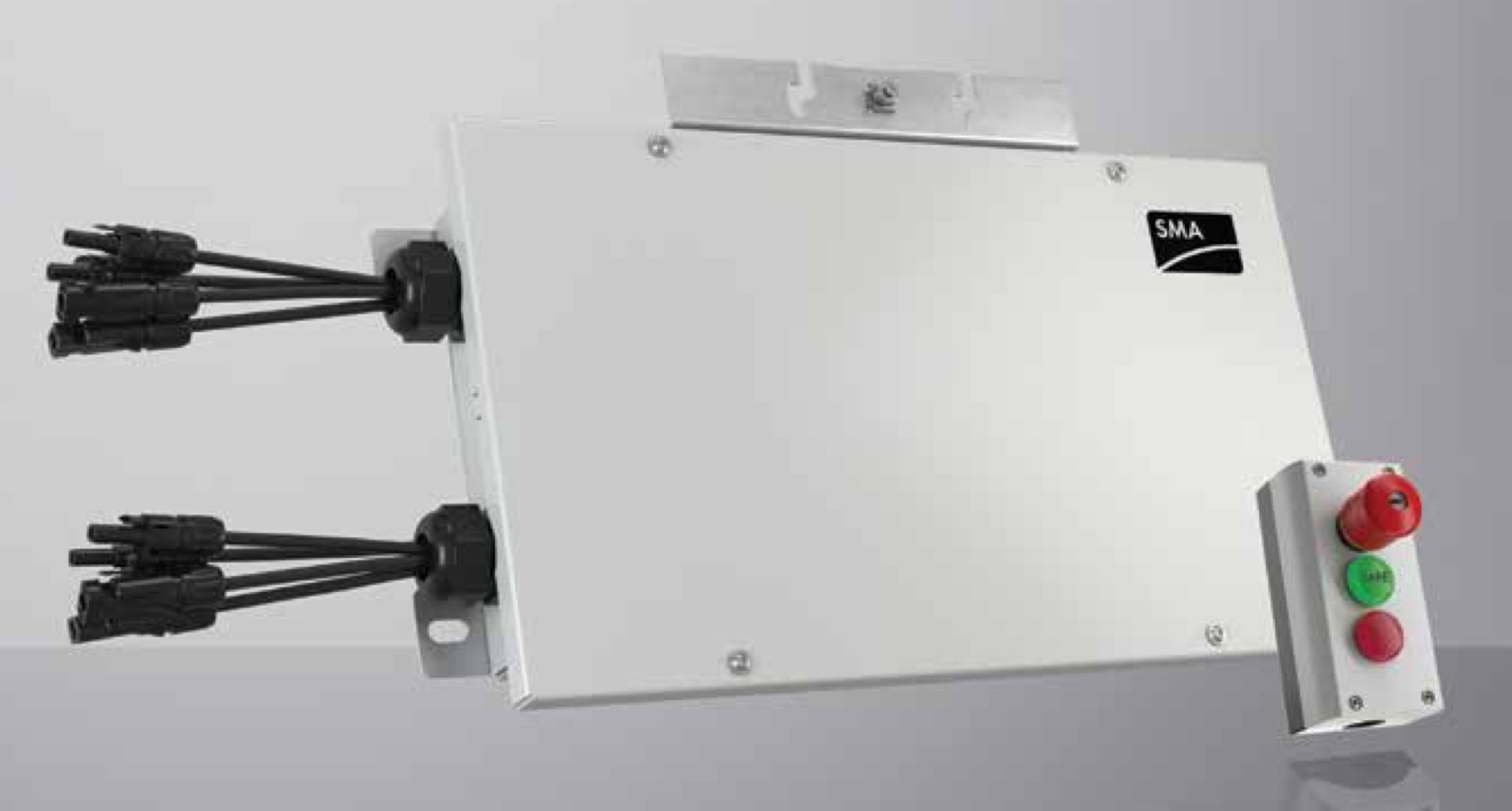
Ron and Kate had met with the local Fire Chief, Fire Marshalls and Fire Captains to explain the NEC PV rapid shutdown requirements in the 2014 and 2017 Codes (690.12, photo 1). The Fire Service personnel had already been involved in discussions with their own organizations about the changes in the NEC with respect to rapid shutdown and had made input through their channels to the Code requirements. They all met on several occasions and worked through the actual Code language as well as looking at requirements in the fire codes and what the local fire departments felt was the best method of implementing those Code requirements at PV installations. Agreement was reached between the electrical inspections and the Fire Service personnel and those agreements and requirements, as interpreted from the NEC requirements, were distributed to the various PV installation organizations in the area. This information primarily dealt with signage and the location of the rapid shutdown initiation device, as well as how these systems would be tested for proper operation.
When it came to the utility connection discussion, Ron and Kate along with the other electrical inspectors worked through Section 705.12 paragraph by paragraph along with the explanations in the NEC Handbook and articles by several people in the IAEI News and in other magazines like Solar Pro. Although their jurisdiction was still using the 2014 NEC, they carefully reviewed the 2017 NEC requirements also, since that Code was to be adopted momentarily and had additional clarification on the requirements that had been in the previous Code.
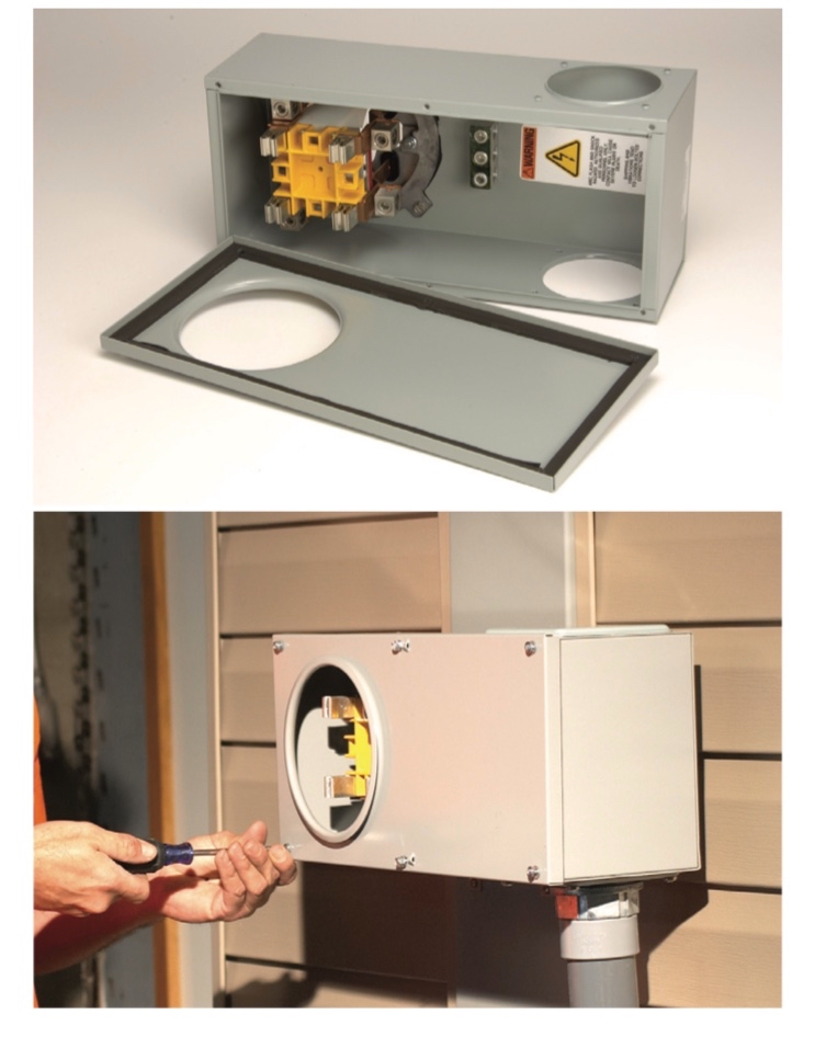
Section 705.12 (A) dealing with supply-side connections was covered thoroughly with some input by Paul who had previously been an electrical inspector. It was decided that the circuit from the actual point of connection on the service entrance conductors to the first overcurrent device/disconnect on the PV circuit would be treated in the same manner as the service entrance conductors in terms of conductor type, routing, and mechanical protection (Photo 2). Unfortunately, they found that the Code did not specifically address the size of these conductors. They decided that these unprotected PV conductors that were exposed to the same available fault currents that the service entrance conductors were exposed to should be as short as possible, particularly if the service had very large conductors and the PV circuit conductors were significantly smaller. Of some concern was the allowance in 705.31 of a 10-foot distance of unprotected conductors from the service conductor connection point to the first PV overcurrent protection/disconnect. Kate had seen an installation with a 2000-amp service entrance “tapped” with a 12-gauge, 20-amp conductor running eight feet into the building to the PV disconnect/overcurrent protection. Aside from the fact that the paralleled service entrance conductors were not “tapped” equally as required by section 310.15(H), that 12-gauge wire would have made a spectacular (burning) fuse if a fault had occurred in that unprotected conductor. They decided that such conductors should be protected to the greatest extent possible, using RMC where possible, and be kept to the minimum practical length.
Section 705.12 (B) required several meetings to cover thoroughly. After significant discussions, the electrical inspectors decided that section 705.12 (B) (1) does not restrict PV system connections to a single overcurrent protective device for each service. Multiple PV systems may be combined through an ac inverter combining panel to a single backfed overcurrent protective device or they may be connected to separate individual overcurrent protective devices as long as the subsequent requirements in the section were met. Although this section has been rewritten several times in successive editions of the Code, they felt that it did not clearly establish requirements for load-side backfed PV system connections.
Section 705.12 (B) (1) came under detailed scrutiny when it was noted that there was no requirement established for feeders where the utility source and the PV source were at opposite ends of the feeder. It was decided, since the currents from these two sources are in opposition and cannot sum together and overload the feeder, that the feeder ampacity should not be less than the rating of the largest overcurrent device on either end. Kate was aware of a proposal for the 2020 NEC that addressed this omission.
In Section 705.12 (B) (2) (2) addressing taps, the discussion group noted that the requirements apply both to existing taps which might have to be modified when PV is added to an existing electrical system, and also to new taps on the circuit where PV had been previously installed. This indicated that some sort of marking on that circuit should be required indicating that any new taps must comply with this section of the Code.
The group noted the change in 705.12 (B) (2) (3) (d) that now allows a PV connection at one, but not both, ends of a center fed panelboard with the application of the 120% rule. Kate had worked on a proposal for the 2020 NEC that would allow PV connections at both ends while still restricting the total PV contribution of both PV breakers and the main breaker to 120% of the busbar rating. This new allowance should reduce the possibility of overloading a center fed panelboard due to PV connections where PV inverter outputs are connected to both ends of the busbar rather than just one end.
As she went through the pile of permitted PV systems, she looked for the open-circuit voltage calculation which is based on the expected ambient temperature at the installation location. Many new PV modules are entering the market and some of those modules use cell technology other than the standard silicon, CAD Telluride or other common materials. These new technologies would require a calculation based on the module temperature coefficients and the expected low temperature. The jurisdiction, working with PV systems integrators and installers, had decided on and expected low temperature throughout the jurisdiction of 14°F (-10°C) for these calculations. Occasionally she found another temperature being used which was acceptable if that temperature was lower (more conservative) or higher with sufficient justification such as a documented (with data) heat bubble on the roof of an industrial building roof.
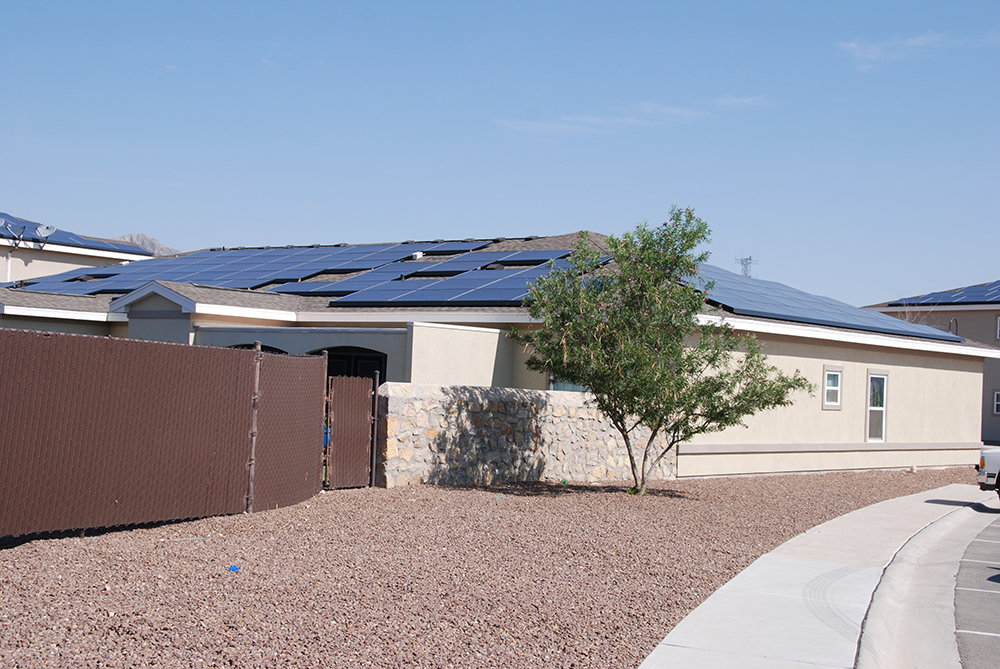
Although Kate’s jurisdiction allowed inspectors to go on the roof (with a ladder provided by the system installer), she found it difficult to verify module and string conductor sizes, connectors (male/female) from the same manufacturer and grounding provisions on PV arrays mounted close to the roof (photo 3). Therefore, the jurisdiction required that these details be fully specified in the permit application along with pictures of the mounting and grounding provisions. Those provisions were then compared to the instruction manuals for the PV modules and the racking system. Pictures and specifications were also required for all module and string connectors used in the dc system to ensure that they were from the same manufacturer and in the same series. Kate and Ron both knew that connectors from different manufacturers, although they appeared to be electrically and mechanically compatible, had not been certified/listed for use together and could pose significant long-term safety hazards and performance issues.
The scope of UL Standard 2703 for PV racking systems (use not specifically required by the Code) does not cover the manner in which the rack is attached to the roof. Since many of the houses and commercial buildings in the jurisdiction had low slope roofs with no access to the underside of the roof, the PV installers were required to indicate in some detail how they were attaching the racking system to the roof and the method they were using to determine the location of various structural members to which the racking system attached. High winds in this area of the state precluded attachment of PV racking systems directly to the typical ½- 9/16-inch-thick roof sheathing. On commercial roofs, the installer had to supply a structural assessment of the roof and any details on using ballasted gravity or adhesive attachment methods.
Kate enjoyed and looked forward to doing plan review on systems that were being installed by organizations that had done numerous PV systems in the jurisdiction. These companies usually had several NABCEP (North American Board of Certified Energy Practitioners) certified installers and system designers. They provided professionally done CAD drawings showing three-line diagrams clearly showing all conduit sizes, all conductor sizes, ampacity calculations for each circuit segment based on the conditions of use and good grounding details. They provided full installation and operation manuals for all electronic equipment including the PV modules, any dc to dc converters, charge controllers (where used), inverters, combiners, and energy storage devices or the new AC battery systems. They provided cut sheets with manufacturer’s specifications for the more mundane pieces of equipment such as disconnects, load centers, panelboards and the like. Where nonstandard conductors were being proposed, full manufacturers specifications were provided. All calculations with respect to conductor and conduit sizing, overcurrent device ratings and Section 705 Code requirements were carefully and completely presented. These types of plan reviews were a pleasure to perform. And Kate found that when inspected, these installed systems usually complied fully with the previously approved system permit, the diagrams and the installation details. Furthermore, these highly professional PV systems integrators and PV installers were always ready for the inspection with a ladder for roof access and a knowledgeable person on-site that could answer any questions she had. They usually brought substantial amounts a backup data to ensure that she was satisfied with the safety of the installation.
End of the Day
Kate had completed 12 plan reviews during the day and had a chance to watch a manufacturer’s web-based tutorial on a new inverter product and a tutorial on a dc to dc converter that coupled with a mating PV inverter. She reviewed literature on several devices including an instruction manual on a PV rapid shutdown system that could be installed with nearly any string inverter up to 15 kW.
Ron had called in and said he was feeling better and should be in the next day. Although the storm was unabated outside, the weather report called for fair skies in the morning. She closed up her office for the day and headed for the garage, not looking forward to the hour-plus commute and a hungry dog and cat at home. Hopefully, the storm would fade out during the night and they would all get some rest for the upcoming day of inspections. As she drifted off to sleep, she had visions of a clear sunny day when PV systems and electrical inspectors were hard at work.
Summary
Although the events and people depicted above are fictionalized, the training and continuing education of Plan Reviewers and Inspectors are absolutely essential to having qualified, competent, professional people that are fully capable of discharging the responsibilities of ensuring the safety of the public. The increasing complexity of PV systems and the manner in which they are installed dictate that a plan review stage be incorporated into the inspection process. That plan review stage may be accomplished by a dedicated Plan Reviewer (preferred) or by the Inspector allocating time in the office for plan review.
For More Information
The author has retired from the Southwest Technology Development Institute at New Mexico State University but is devoting about 25% of his time to PV activities to keep involved in writing these “Perspectives on PV’ articles in the IAEI News and to stay active in the NEC and UL Standards development process. Seven to eight-hour presentations are still available on PV and the Code and they cover 2011-2017 NEC requirements. He can be reached at: e-mail: jwiles@nmsu.edu, phone: 575-646-6105
The Southwest Technology Development Institute web site maintains a PV Systems Inspector/Installer Checklist and all copies of the previous “Perspectives on PV” articles for easy downloading. A color copy of the latest version (1.93) of the 150-page, Photovoltaic Power Systems and the 2005 National Electrical Code: Suggested Practices, written by the author, may be downloaded from this web site: https://swtdi.nmsu.edu/codes-standards