Article 725 in the NEC covers signaling systems and remote control systems. These types of systems are not always easily distinguished from each other because applications of signaling and remote control circuits tend to overlap. In fact, some systems or circuits often perform both functions. For this reason, the rules in Article 725 and the application of those rules are based on circuit classifications rather than precise functions. (The terms remote control and signaling will be treated as interchangeable in this article.)
Remote control and signaling circuit classifications are based on usage and power limitations. Because of the power limitations and the limited uses of the circuits covered by Article 725, special wiring methods and installation requirements apply. Article 725 modifies the first four chapters of the NEC with regard to some alternative wiring methods, and provides somewhat relaxed requirements in other respects. However, in order to maintain the power limitations upon which the special rules are based, other requirements are somewhat more restrictive, particularly those that relate to separations from higher-powered circuits and systems.
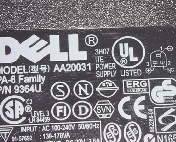
Photo 1. Example of a listing mark for a power supply for information technology equipment
The wiring covered by Article 725 is often called low voltage wiring. However, the scope of Article 725 encompasses more than is implied by this term and the meaning of low voltage is entirely dependent on context when used in the NEC. For example, Article 490 defines high voltage as more than 600 volts, which indicates that low voltage is anything 600 volts or less. In fact, the title of Section 110.34(B) includes the term low voltage and it means 600 volts or less in that context. Yet in another part of the same article, specifically Section 110.26(A)(1)(b), low voltage means not greater than 30 volts rms or 42 volts peak in ac systems or 60 volts in dc systems. Other levels of voltage are used to determine the applicability of special rules for lighting, such as 30 volts or less in Article 411 and 15 volts or less in Sections 680.24(A)(2) and 680.33(A). Low voltage is defined in 551.2 as 24 volts nominal or less for applications in recreational vehicles. The point is that low voltage is simply not a good description or definition for signaling circuits nor does it accurately describe the scope of Article 725.
Limited energy or power limitedare more meaningful terms in describing how the NEC defines circuits used for signaling and remote control, but even these terms have specific meanings only
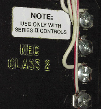
Photo 2. Typical marking that identifies a Class 2 source on a listed garage door opener
in certain contexts. According to Section 725.21(A), Class 1 power-limited circuits are allowed to have higher power ratings than Class 2 or Class 3 circuits [see Tables 11(A) and 11(B) in chapter 9] and power supplies for power-limited fire alarm circuits are treated as equivalent to Class 3 sources in Section 760.41. The only accurate way to refer to signaling circuits for use in applying the NEC and Article 725 is through the identified circuit classes defined and used in Article 725. However, some circuits that may appear to perform signaling functions may actually be classified as fire alarm circuits covered by Article 760 or may perhaps be classified as communications circuits covered in chapter 8.
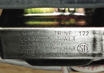
Photo 3. Class 3 power supplies if the circuits are used in wet locations as shown
Article 725 defines three classes of signaling circuits: Class 1, Class 2, and Class 3 circuits. Class 1 circuits are further subdivided into Class 1 power-limited circuits and Class 1 remote-control and signaling circuits. (Although this distinction is made to differentiate power sources for Class 1 circuits, this distinction is not used with regard to wiring methods or other installation rules that apply to Class 1 circuits in Article 725.) The circuits themselves are defined by their power supplies in accordance with Section 725.21 for Class 1 circuits and 725.41 for Class 2 and Class 3 circuits. In other words, a user or inspector need only locate the power supply and examine its rating and/or listing in order to determine the class of the circuit in question.
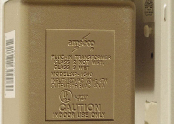
Photo 4. Typical plug-in Class 2 or 3 power supply transformer
Class 2 circuit applications are much more common than Class 3 circuits. But circuits are neither Class 2 nor Class 3 just because they are at some “low voltage” such as 24 volts. Most of the time a circuit must be supplied by a source that is listed as a Class 2 or Class 3 source in order for it to be a Class 2 or Class 3 circuit. However, some equipment that is listed other ways may supply Class 2 circuits. For example, the limited-power circuits of listed information technology equipment (ITE) are recognized by 725.41(A)(4) as Class 2 circuits. An example of this listing mark is shown in photo 1. Photo 2 is an another example of typical markings that identify a Class 2 source on listed equipment, in this case, a garage door opener. Other sources that are not labeled as Class 2 but are newly recognized in the 2005 NEC are the limited power supplies of other listed equipment such as power-limited input/output or communications circuits of listed industrial control equipment. These circuits are widely used in programmed logic control systems and industrial machinery. This new rule is found in 725.41(A)(3), Exception No. 2 and explained in the related fine print note.
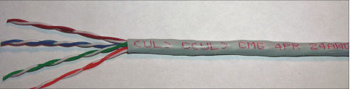
Photo 5. 4 pair Category 5 Type CM cable (general purpose)
In some cases, Class 2 or Class 3 circuits are permitted or required to be reclassified as Class 1 circuits [see 725.11 and 725.52(A), Exception No.2] or permitted or required to be reclassified as communications circuits [see 725.55(D)(2)(b) and 725.56(D)(1)]. As noted in 725.52(A), Exception No. 2, FPN, where circuits are reclassified, they are reclassified for their entire length and must comply with all of the requirements for the new classification.
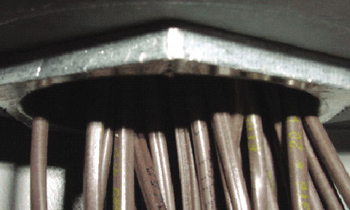
Photo 6. Example of a raceway used for cable management and physical protection where raceway fill applies to the Class 2 circuits, but where adjustments factors do not apply
The fine print note that follows Section 725.1 explains why special classifications are applied to signaling circuits. The difference between power and lighting circuits and Class 1, Class 2, and Class 3 circuits is twofold: one, usage, and two, power limitations. Class 1 circuits are primarily distinguished by usage as they are permitted to be supplied by sources that could initiate a fire and could be a shock hazard, and in some cases may even have less restrictive overcurrent protection requirements than branch circuits. However, as described in 725.2, Class 2 and Class 3 circuits have significant power limitations that keep either from initiating a fire under normal conditions and keep Class 2 circuits from presenting a shock hazard under normal conditions. A lower level of voltage may be a shock hazard in a wet location than would be a hazard in a dry location. For this reason, some power supplies are listed as Class 2 power supplies in dry locations but become Class 3 power supplies if the circuits are used in wet locations as shown in photo 3. Typically, 30 volts rms is considered to be the threshold of shock hazard in dry locations and 15 volts rms is the threshold for wet locations. This information may be found in the notes to Table 11(A) in chapter 9. Photo 4
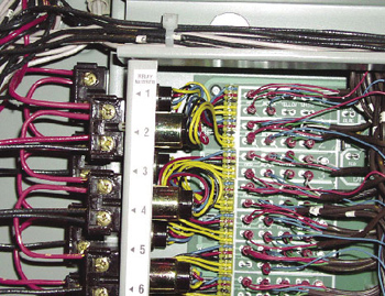
Photo 7. Example of separations maintained by barriers within an enclosure
The fine print note following 725.1 also explains how Article 725 modifies the general rules of chapters 1 through 4 of the NEC. Article 725 allows the use of smaller wire sizes than would be allowed for branch circuits and permits additional uses of fixture wires (insulation types) that are not mentioned in Article 402. It changes the application of derating factors, specifically the adjustment factors of 310.15(B)(2)(a), for most signaling circuits. It modifies the requirements for overcurrent protection, primarily because the loads are relatively small and conductors are not subject to overloading, or because the power sources are inherently limited. And, especially for Class 2 and Class 3 circuits, Article 725 allows the use of wiring methods — primarily special cable types — that are not permitted for higher-powered circuits. (Article 725 does not provide or permit any special wiring methods for Class 1 circuits.) As noted previously, in exchange for these “loosened” rules, Article 725 modifies Article 300 in requiring that, in most cases, signaling circuits be separated from higher powered circuits so that inadvertent contact with higher powered systems will not compromise the power limitations of the power supplies that define the classes of signaling circuits. Although Article 725 does not specifically mention it, the rules for grounding many signaling circuits and related equipment are also different from the rules for power and lighting circuits. These modifications are found within Article 250 itself. We will briefly examine each of these types of modifications in the remainder of this article.
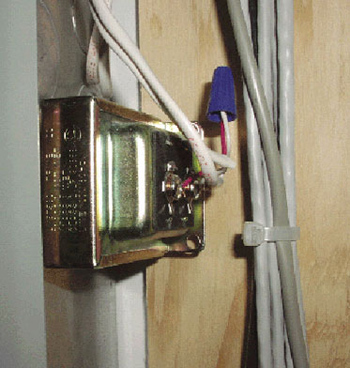
Photo 8. Class 2 transformer
Perhaps the most evident difference between signaling circuits and power or lighting circuits is the permitted use of special cable types for wiring. These special cable types are permitted because of the inherent energy limitations of Class 2 and Class 3 circuits and their power supplies. The special wiring methods that may be used for Class 2 and Class 3 circuits are outlined in Section 725.52(B). In addition, Section 725.52(A) allows the use of Class 1 wiring methods and also allows Class 2 or Class 3 circuits to be reclassified as Class 1 circuits.
Reclassification of a circuit is significantly different from using the wiring method of another class of circuit. The use of Class 1 methods is permitted for a portion of a Class 2 circuit, but a reclassified circuit becomes a Class 1 circuit for its entire length as noted in the fine print note that follows 725.52(A), Exception No. 1. A similar distinction must be drawn between the permitted substitution of communications cables for Class 2 or Class 3 cables and the reclassification of the Class 2 or Class 3 circuits as communications circuits. Nevertheless, either way, a different cable type or wiring method is permitted or required. For example, the typical intended use of 4 pair Category 5 Type CM cable like that shown in photo 5 is for a combination of Class 2 and communications circuits, but since both types of circuits are within the same cable in this case, they must all be classified as communications circuits in accordance with 725.56(D)(1) and 800.133(A)(1)(b). If the cable were used for only Class 2 circuits, the cable could be used as a substitute cable in accordance with 725.61(G) and the circuits would remain classified as Class 2.
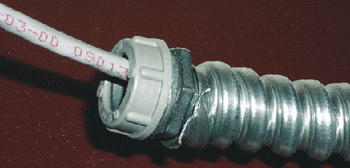
Photo 9. Raceway containing only 24-volt, Class 2 circuits that are derived from a 120-volt system
There are no special wiring methods for Class 1 circuits according to 725.25, and methods from chapter 3 must be used. However, 725.25, Exception No. 1 recognizes the smaller conductor sizes and insulation types permitted by 725.27. The alternative insulation types are certain types of fixture wires covered by Article 402, but in this case fixture wires are allowed to be used in applications that are beyond the scope of Article 402 and that are not mentioned in Article 402. All Class 1 circuits, even those that are less than 30 volts, must use insulation rated for 600 volts, but wire sizes are permitted to be as small as 18 AWG. Wire sizes for Class 2 and Class 3 circuits are not specified by the NEC. Where the cables listed for Class 2 and Class 3 are used, the listing standard for the cables includes a minimum conductor size for construction of such cables.
The uses and applications of the special cable types described in 725.61 and 725.82 are too numerous to review in detail in this article. However one common problem relates to the use of cables in ducts, plenums, and other spaces for environmental air as described in Section 300.22. An important point to note is that since 725.3(C) requires compliance with 300.22, all permissions for uses of cables in ducts, plenums, and other spaces for environmental air must be interpreted and applied to also comply with 300.22. For example, although Section 725.61(A) seems to permit installations of “plenum-type” cables (with the suffix “P” in their markings) to be installed in ducts, Section 300.22 permits such “equipment” only where necessary for direct action or sensing of the contained air. Wiring is equipment as defined in Article 100. Other Class 2 and Class 3 cables may be used as outlined in 725.61 within the limits of their listings as given in 725.82.
Section 725.28(B) says that the adjustment factors from Table 310.15(B)(2)(a) apply only to Class 1 conductors that are loaded to more than 10 percent of their ampacity. Where Class 1 methods are used for Class 2 or Class 3 circuits, the adjustment factors do not apply. It follows, although it is not specifically stated, that adjustment factors would not apply to Class 2 or Class 3 conductors installed using Class 2 or Class 3 wiring methods, but where Class 2 circuits are reclassified as Class 1 circuits, all requirements for Class 1 circuits do apply. [See 310.15(B)(2), Exception No. 1 which explains that adjustment factors are intended to apply only to power and lighting conductors.] Whether adjustment factors apply or not, Section 725.3 requires compliance with raceway fill limits for all circuits covered by Article 725. Note, however, that if Class 2 or Class 3 circuits are reclassified and installed as communications circuits as covered in 725.56(D), neither adjustment factors nor raceway fill limitations apply [See 90.3 and 800.110, Exception]. Photo 6 shows an example of a raceway used for cable management and physical protection where raceway fill applies to the Class 2 circuits, but where adjustment factors do not apply.
Section 725.23 provides overcurrent protection requirements for Class 1 circuits. “Derating” factors of 310.15, that is, the adjustment factors of 315.15(B)(2)(a), are not applied in determining ampacities and the small conductor rules do not apply in accordance with 240.4(D) and (G) for conductors 14 and larger. Overcurrent protection may not exceed 7 amperes and 10 amperes for sizes 18 AWG and 16 AWG respectively. [These maximum values of overcurrent protection are not the ampacities of 18 and 16 AWG. Loads are limited to the ampacities given in Table 402.5 according to 725.27(A) where the ampacities are given as 6 amperes for 18 AWG and 8 amperes for 16 AWG.] The overcurrent protection is located as required by 725.24. These rules are similar in many ways to the rules of 240.21, and in some cases, larger overcurrent devices or overcurrent protection on the supply side of a power supply may be adequate. No additional overcurrent protection is required for Class 2 and Class 3 circuits because the power supplies are inherently limited.
In order to ensure the integrity of the power limiting means for signaling circuits, physical separations from higher powered circuits are required, especially in raceways and cables. For the most part, these requirements are more restrictive than the requirements of 300.3(C)(1) which, according to 725.3, do not apply to the circuits covered by Article 725. Although Class 1 circuits are permitted to be up to 600 volts, they are generally required to be kept separate from power and lighting circuits unless the circuits are functionally associated. But even functional association does not relieve the requirement for maintaining separations between Class 2 or Class 3 circuits and power, lighting, or Class 1 circuits. Class 2 or Class 3 circuits that are reclassified and wired as Class 1 circuits are subject only to the functional association restrictions of Class 1 circuits.
Separation requirements are found in 725.26 for Class 1 circuits and in 725.55 for Class 2 and Class 3 circuits. These sections recognize that signaling circuits will sometimes have to occupy the same enclosure to connect to common equipment, such as to relays that control a lighting circuit and that are, in turn, controlled by a Class 2 circuit. Alternative methods, including barriers, raceways within enclosures, or in some cases, physical distance or cable jackets, must be used to maintain separations within enclosures as specified in Section 725.55. Photo 7 shows an example of separations maintained by barriers within an enclosure. Photo 8 shows power wiring on the inside of an enclosure separated from Class 2 wiring on the outside where the terminals are allowed to be exposed on the outside because they do not present a shock hazard. Class 2 transformer like the one shown in photo 8 are often found where a single box is used to contain supply conductors, the power supply, and the Class 2 wiring for installations of doorbells, and these installations violate separation rules in most cases.
Grounding requirements of equipment and circuits covered by Article 725 are not specified in Article 725. As mentioned previously, the “special rules” in this case are actually found in Article 250. Where equipment such as boxes and raceways are required to be grounded or bonded, the requirements for signaling circuits are no different than for other circuits and systems. However, many signaling circuits and related enclosures and metal parts are not required to be grounded.
To determine whether raceways and other metal enclosures for signaling use are required to be grounded, we must first determine whether the system is required to be grounded, that is, whether the voltage system is required to include a grounded conductor. This can be determined from 250.20 in most cases (see 250.162 for dc systems). On one hand, according to 250.20(A), most Class 2 systems used for such purposes as doorbells, garage door openers, and thermostats are not required to be grounded because they are less than 50 volts, are derived from grounded 120-volt systems, and are not installed as overhead conductors outside of buildings. On the other hand, a 120-volt, Class 1 circuit would usually have to be grounded in accordance with 250.20(B)(1). Second, according to 250.112(I), the equipment supplied by these circuits is only required to be grounded where system grounding is required by Part II (250.20) or Part VII (250.162). Thus the equipment supplied by or containing the Class 2 circuits in this example is not required to be grounded but the equipment associated with the Class 1 circuits mentioned is required to be grounded. These requirements are reiterated by 250.86, which refers specifically to 250.112(I). The raceway shown in photo 9 is not required to be grounded because it contains only 24-volt Class 2 circuits that are derived from a 120-volt system.
A circuit or equipment that is not required to be grounded by the rules discussed so far in Article 250 may be required to be grounded or bonded in other cases and by other rules. These requirements may be found in Article 725 or in other articles. For example, Section 725.57 imposes additional requirements on Class 2 and Class 3 circuits that extend beyond one building and are subject to accidental contact with higher voltages. In such cases, the Class 2 or Class 3 circuits are required to be treated as communications conductors in certain ways which may include connections to grounded primary protectors and grounding of metallic cable sheaths or shields. In addition, non-current-carrying metal parts of all electrical systems must be bonded in hazardous (classified) locations. Raceways or enclosures may not always be required for signaling circuits in such areas if the circuits are also nonincendive or intrinsically safe, but where metal raceways or enclosures are used in hazardous areas, they must be bonded to comply with Section 250.100.
This article has briefly examined why and how signaling circuits are given special or different treatment in the NEC. The classifications of the circuits covered by Article 725 are determined and differentiated by use and power limitations. Class 2 and Class 3 circuits are most commonly defined by listed power supplies. The inherent power limitations of these supplies justifies the use of alternative wiring methods and different schemes for protecting equipment and persons from the possible hazards of these systems. In fact, in many cases the hazards are already significantly reduced by the nature and sources of the circuits themselves. Article 725 provides somewhat relaxed requirements for installations of signaling circuits. However, in order to maintain the power limitations upon which the relaxed rules are based, requirements for separations from higher-powered circuits and systems must be significantly more restrictive, and these restrictions must be carefully observed.