Sometimes we have a tendency to focus on the complex and assume the basics are common knowledge. A task like terminating conductors just may fall into that category. I could argue that landing conductors and terminating them on equipment such as receptacles, lighting fixtures, circuit breakers and more should be high on the list of good examples that give meaning to the statement “the devil is in the details.”Mistakes made when landing conductors on terminals could cause hours of troubleshooting or other types of problems after continued hours of use and aging of the installation. So let’s take another dive into the basics with an exploration of terminating conductors. I think you may see that this task, which quite often is left to the most inexperienced on the job, may deserve closer attention.
Identifiable Problems
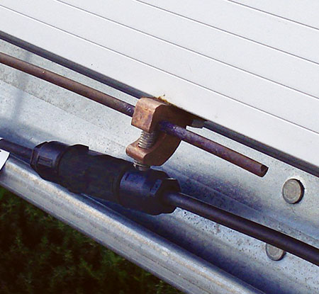
One of the challenges in our industry is that you can’t see that with which we work. You can’t see the electrons and you can’t watch current flowing through the conductors and terminations. Some problems are not noticeable until well after we have left the job as there may not be an immediate cause and effect when it comes to terminations gone wrong. Some problems may take quite some time to manifest themselves. Take the problem in photo 1 as an example. This picture shows the use of an incorrect lug on a photovoltaic panel. The dissimilar metals have caused corrosion to occur over time. I am quite sure that when it was first installed it looked great; time has revealed the weak link.
The following are some identifiable problems that poor terminations can cause.
Heat: Loose connections, those that have either not been torqued properly or installed without any intention to torque, can come loose over time and introduce impedance that reacts with current to cause heat. Some may call these glowing connections. The heat generated acts to further degrade the connection point. Excessive heat at a termination can damage equipment on either side of the termination whether it be the insulation of the conductor or the equipment to which the conductor is attached.
Oxidation: I’m pretty sure I’m safe when I say we are all familiar with oxidation; we’ve all experienced rust and have probably seen that nice green glow on copper. Aluminum is not immune to oxidation as it develops a layer of oxide when exposed to air. This oxidation is highly resistive which translates into heat when it is called upon to carry current. The oxide layer is only a few nanometers thick and so when terminated properly, the mechanical connection breaks the thin, brittle layer of oxide to form an excellent electrical connection. With a continuous proper connection, oxygen cannot penetrate to form further oxide at the termination.
Corrosion: Dissimilar metals can introduce galvanic corrosion. See Photo 1. Galvanic corrosion is caused when two metals are exposed to an electrolyte. The result is an attack on one metal at the expense of the other. This acts to introduce more impedance into the circuit and if this connection is your ground return path or an equipment grounding system, your path of least resistance can be compromised and your grounding system not quite as effective as you had hoped.
Thermal Linear Expansion Coefficient: This is the fractional change in length of a particular material, for each degree of temperature change. Thermal linear expansion can cause loose connections which could result in heating. Applying products as specified by the manufacturer which align with how they are tested per product standards is important for success in this area as well.
Creep: Creep is the continued deformation of material under stress. The aluminum alloy 1350 which was used many years ago and associated with problems years ago, no longer an issue, had a much higher creep rate than copper.
Voltage (Over / Under): If a termination is not made correctly and the wire to the load or from the source does not make the connection needed, you may experience a reduced voltage or even an overvoltage. Your overvoltage condition is a good example of losing the neutral on the line side of, say, a residential home’s main loadcenter. A handful of examples of this have come across my desk where the neutral from the utility, in the meter or even at the transformer, caused an overvoltage in a home resulting in damaged electronics.
Arcing: Arcing from phase to phase, phase to neutral or even phase to ground can occur if bare conductors touch equipment or other bare conductors. Stripping insulation from the conductor before termination and damaging the insulation during termination can introduce opportunities for arcing faults to occur.
NEC Violation: As you will see below, there are many areas in the code that focus on termination points. When mistakes are made, an inspector just may be able to point out the problem and the NEC section it violates.
Misoperation: Improper voltage, high impedance paths and arcing and sparking as well as other effects of poor terminations may cause equipment to not operate as expected. Whether it be sensitive electronic equipment, industrial control equipment or a grounding system solution or more, mistakes in terminations may be a cause of misoperation.
Violate UL Listing: If care is not taken in your terminations, you may be applying the product outside of its UL listing. Products are tested under certain conditions and test configurations. These are reflected in manufacturer instructions and can be found in the UL White Book. When a product is applied incorrectly, the safety of the application could be at risk as the configuration may have never been tested.
These highlighted items are just some of the issues that can be experienced when terminations go wrong. There are indeed more examples and the act of exploring these and more is a great way to engage with others on this topic. The act of sharing experiences and examples can help create a healthy dialog that will increase the level of education of all involved.
There are two ends to every conductor, both of which must be terminated. Explore the requirements around the terminations on both ends of each conductor. The limiting factor will be the weakest link that may cause the derating of the entire length of conductor. Temperature ratings is a good example of this. Landing a 90°C insulated conductor on a 75°C terminal has ramifications that impact the ampacity that can be used for that conductor. If one of the two terminals are 75°C and the other is 90°C, the limiting factor is the 75°C conductor which will command that the ampacity of the conductor be limited to that associated with its 75°C rating. Then too, just because the lug says 90°C does not mean that you can still use it and apply it as a 90°C rating; the equipment in which the lug is installed may have limitations with this regard. It is very important to understand the equipment / products being installed and their limitations to ensure terminations are in line with manufacturer and product standard requirements.
Codes and Standards
Codes and standards exist for safety. The following National Fire Protection Association (NFPA) sections are a great place to start in your quest to learn more about proper terminations:
Section 110.3(B) Installation and Use: This is an important section as it is a reminder that listed or labeled equipment shall be installed and used in accordance with the instructions included in the listing or labeling. Set your instructions aside for review and don’t go dumpster diving for them after the job is done and problems arise. Inspectors and installers should take the time to review these documents and not take the rocky road of assuming that the new product you are installing is the same as all of the other “similar” products you install or that the product you install today is the same as how that same product was installed 5 years ago. Designs change from one product to the next and as time goes on manufacturers improve and modify products and can impact how they are to be installed and how conductors must be terminated. Stay up-to-date and don’t make assumptions. Manufacturers’ product announcements can be a trigger to update your knowledge on the products you install.
Section 110.11 Deteriorating Agents: This section focuses on the proper application of products recognizing that external sources can have a deteriorating effect on conductors and/or equipment. There are two documents available from NEMA, one of which was just recently released, that reference this section of the code heavily in that these documents try to address how products are impacted by flooding and fire/smoke damage.
The document titled “Evaluating Water-Damaged Electrical Equipment” is a free download from NEMA and available at http://www.nema.org/Standards/Pages/Evaluating-Water-Damaged-Electrical-Equipment.aspx.
The document titled “Evaluating Fire- and Heat-Damaged Electrical Equipment” is a free download from NEMA and available at http://www.nema.org/Standards/Pages/Evaluating-Fire-and-Heat-Damaged-Electrical-Equipment.aspx.
These are great resources for the electrical industry and provide good examples of how external sources can have a deteriorating effect on electrical equipment including conductors.
Section 110.12: Mechanical execution of work: Neatness counts and in terminations it can make a world of difference. This section reminds us of our need to focus on neat work. On any one job, terminations could be overwhelming in number. Neatness in work can help bring that level of clarity to your project so mistakes are not made.
Section 110.12(B): Integrity of Electrical Equipment and Connections: Protection of key components in your equipment is important to ensure that terminations are of good integrity. Terminating on lugs that have been contaminated with paint or other foreign materials could be a problem.
Section 110.14: Electrical Connections: This section addresses dissimilar metals, fine stranded conductors and necessary termination details and more. This section of the NEC includes very good information and requirements for Terminals [110.14(A)], Splices [110.14(B)] and Temperature Limitations [110.14(C)]. Materials such as solder, fluxes and more are discussed as well within 110.14. In addition to code requirements, consult the UL White Book and the manufacturer’s instructions.
There are many more sections in the Code that are important to effective terminations but the above can get you started. Knowing the Code and continuing studies as it changes will help in your effort in attention to the details.
Another important resource is the UL White Book and associated UL standards. The following categories can provide important information that will help in the understanding of how to apply products.
AALZ: Electrical Equipment For Use In Ordinary Locations
ZMOW: Wire-Connector Adapters
ZMVV: Wire Connectors and Soldering Lugs
ZMWQ: Sealed Wire-Connector Systems
The UL standards of most importance, in addition to individual product UL requirement documents, are shown below. Note that the White Book is a free resource that contains all of the application information you need to know from the following standards:
UL 486A – 486B: Wire Connectors
UL 486A: Wire Connectors and Soldering Lugs for Use With Copper Conductors
UL 486B: Wire Connectors for Use with Aluminum Conductors
UL 486C: Splicing Wiring Connectors
UL 486D: Sealed Wire Connector Systems
UL 486E: Equipment Wiring Terminals for Use with Aluminum and/or Copper Conductors
The UL White Book is a free download from the UL website.
Key Takeaways
Care should be taken when making terminations. Often, this work is left to the most inexperienced of the team. These individuals must understand how important their task at hand is and understand code and product requirements that directly pertain to their work. Share your knowledge and together follow the continued development of the NEC.
As always, keep safety at the top of your list and ensure you and those around you live to see another day.