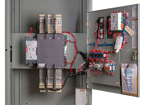
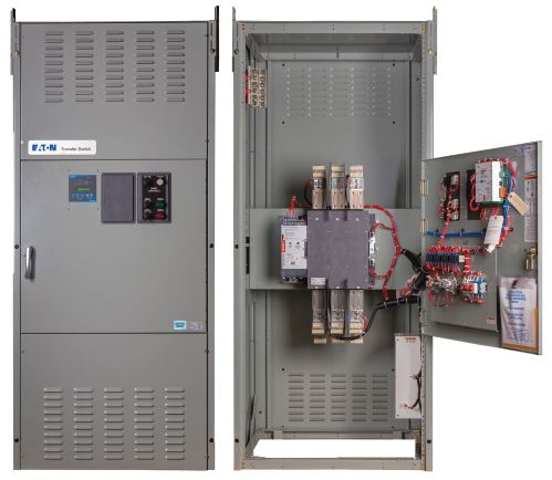
A transfer switch (automatic or manual) is a key component for switching between the normal and alternate power source. Proper transfer switch selection is more than simply determining the operation mode (such as automatic or manual, and open or closed transition), load types, and voltage and continuous current ratings. From an electrical safety perspective, the short-circuit current rating (SCCR) may be the most important rating of all. However, this rating is often overlooked. Figure 1 is a transfer switch example.
The transfer switch marked SCCR values can vary based on the voltage and overcurrent protective device (OCPD) type, amp rating, settings and characteristics. The OCPD protecting the transfer switch may be integral to the transfer switch, but typically it’s installed external of the transfer switch equipment. This can create challenges for the electrical engineer in the design phase since the ratings from various transfer switch manufacturers can vary and the OCPD protecting the transfer switch can vary based upon the manufacturer providing the electrical distribution equipment for the project.
UL® 1008 Transfer Switch Equipment requires transfer switches to be marked with an SCCR. Transfer switches are typically factory marked on the inside of the unit with multiple possible SCCR levels with each dependent on different overcurrent protective device characteristics. This makes it challenging for installers and inspectors to determine the actual transfer switch SCCR once it’s installed in the field. For a specific installation, it may not be obvious which one of the multiple transfer switch SCCR levels (expressed in kA RMS symmetrical current) is being utilized for the specific installation. For compliance with National Electrical Code (NEC®) 110.3(B) and 110.10, the transfer switch marked SCCR must be equal to or greater than the available short-circuit (fault) current at the point of installation. To assure compliance, the specifying engineer needs to assure the transfer switch being provided is protected with the proper OCPD to achieve the required SCCR level.
UL 1008 SCCR nomenclature
The SCCR nomenclature used in UL 1008 for marking transfer switches make use of terms “short-circuit withstand and closing rating,” “short-time current rating,” or other similar derivatives. Often, “short-circuit withstand and closing rating” is shortened to “withstand and closing rating” with WCR as its acronym. The WCR is applicable when evaluating the transfer switch OCPD — either a circuit breaker with an instantaneous trip (even if it also has a short-time-delay) or current-limiting fuses.
In some cases, a transfer switch is factory marked with an SCCR that’s dependent on a specific manufacturer’s circuit breaker rating. The specific circuit breaker is used during the testing of the transfer switch and the shortest clearing time of the circuit breaker is determined. This specific SCCR, dependent on a specific circuit breaker, can then be extended to other manufacturer’s circuit breakers provided the circuit breaker’s time-current curve shows its maximum clearing time is less than the shortest clearing time of the specific circuit breaker used during the testing. The list of acceptable specific circuit breakers is available from the transfer switch manufacturer.
In lieu of testing with a specific circuit breaker, the transfer switch manufacturer can test with a time based rating (previously referred to as an “any breaker rating”). For transfer switches rated 100 A or less with an available short-circuit current of 10,000 A or less, the time duration can be 0.008, 0.017 or 0.025 second. The time duration for transfer switches rated 101-400 A is 0.025 second for the test current selected. All other ampacity transfer switches use a time duration of 0.05 second for the test current selected. As an option, time durations of 0.067, 0.083 or 0.1 second can be selected. Longer time durations are needed for larger transfer switches intended to be protected by low voltage power circuit breakers with instantaneous trip.
The short-time current ratings are applicable when a transfer switch is being evaluated for protection by low voltage power circuit breakers with a short-time delay (no instantaneous trip) and the interrupting time is intentionally delayed for a duration such as 0.1, 0.3, or 0.5 second. In some applications, circuit breakers with short-time delays are utilized to achieve selective coordination with downstream circuit breakers. However, when a circuit breaker with intentional short-time delay and no instantaneous trip is protecting a transfer switch, the transfer switch must withstand the short-circuit (fault) current for the duration of the set time delay. Therefore, the transfer switch SCCR for “short-circuit current rating” is normally lower than the when a transfer switch is protected by a circuit breaker with instantaneous trip.
The manufacturer of the transfer switch can also test with manufacturer specific fuses or UL Class fuses. Manufacturer specific fuses are permitted where the test current is below the current limiting threshold of the fuse. For test currents up to 10,000 A, any current limiting fuse with Ip and I2t limits equal or greater to that for Class RK5 fuses must be used. For test currents above 10,000 A, any current limiting fuse with Ip and I2t limits equal to or greater to that for Class RK5, J, T or L fuse can be used. These limiter or “umbrella fuses” are purchased from fuse manufacturers who verify the let-through limits comply with the Ip and I2t limits set by Underwriters Laboratories (UL®).
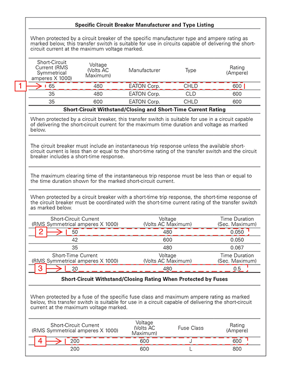
A given transfer switch will typically have several SCCR levels that are marked on the equipment by the manufacturer. Figure 2 illustrates what may be marked on a manufacturer’s label for SCCR with four OCPD categories and comments regarding usage. In all cases, attention should be given to the maximum voltage indicated and the corresponding SCCR.
- Specific manufacturer’s circuit breaker and type
The circuit breaker manufacturer, type (model/catalog number) and amp rating must be explicitly stated, such as Eaton®, CHLD, 600 A. The list of other specific circuit breakers that are also suitable, with voltage and interrupting ratings equal to or greater than the specified voltage and transfer switch short-circuit current rating, is available from the transfer switch manufacturer.
- Short-circuit current withstand and closing with a circuit breaker
Any circuit breaker can be used if it has an instantaneous trip with a maximum clearing time equal to or less than the transfer switch marked time duration. This includes a circuit breaker that has a short-time delay in addition to an instantaneous trip or instantaneous override. The circuit breaker selected must have a voltage rating equal to or greater than specified, and an interrupting rating equal to or greater than the SCCR of the transfer switch. Note how the SCCR of the transfer switch is reduced when compared to the specific manufacturer circuit breaker.
- Short-time current ratings with a circuit breaker
Any circuit breaker with a short-time delay (no instantaneous trip) can be used if the circuit breaker short-time delay setting is equal to or less than the transfer switch marked time duration. The circuit breaker must have a voltage rating equal to or greater than specified with a short-time delay setting not more than specified. In this case the SCCR of the transfer switch is significantly lower than the ratings with specific or any circuit breaker rating.
- Short-circuit current withstand and closing with fuses
Fuses of a specific UL class can be used when not exceeding the maximum amp rating shown in the marking. The fuse must be applied per its maximum voltage rating. Current-limiting fuses have high interrupting ratings of 200,000 A or higher which typically results in a 200 kA WCR (withstand and closing rating). In addition, selective coordination with lineside or loadside fuses is simple if the proper fuses are specified and applied in accordance with published selective coordination amp ratios.
Pass/Fail Criteria
The pass/fail criteria for transfer switches depends upon its type. The transfer switch can be either tested per the requirements for emergency systems or optional standby. Both UL 1008 and the NEC require transfer switches for legally required standby systems to comply with the requirements for emergency systems and be listed for emergency use. The difference is the level of protection and ability to transfer power to the alternate source. Transfer switches for emergency systems must be able to transfer to the alternate source without damage to the alternate source contacts. The transfer must be automatic (electrical) while manual operation is optional. Transfer switches for optional standby systems in Mexico and the United States only need to transfer to the “OFF” position if provided. If no “OFF” position is provided, then it must transfer to the alternate source. Transfer can be either automatic (electrical), manual or both.
The criteria for acceptable damage after the test is the same for all transfer switches. Some key considerations include:
- The enclosure cannot become energized or present a shock hazard (open fuse connected between the enclosure and one phase).
- The switch base cannot be damaged to the extent that that integrity of the mounting of the live parts is impaired.
- The door cannot open, prevented by the enclosure latch without bolt or latch installed.
- Conductors cannot pull out of terminations.
- The interlocking mechanism continues to prevent simultaneous connection to both the normal and alternate source.
- A dielectric voltage withstand test must be passed.
NEC requirements
The 2017 NEC added a new requirement in 700.5(E), 701.5(D), 702.5 and 708.24(E). This new requirement entails field marking of the transfer switch SCCR on the enclosure exterior based upon the OCPD feeding the transfer switch. As noted above, this requirement affects all transfer switches regardless of loads served – whether emergency, legally required standby, optional standby or critical operation power systems. The wording is essentially the same in all sections as shown below from 700.5(E).
700.5(E) Documentation. The short-circuit current rating of the transfer equipment, based on the specific overcurrent protective device type and settings protecting the transfer equipment, shall be field marked on the exterior of the transfer equipment.
So why was this marking requirement added to the 2017 NEC? The panel statement from Code Making Panel (CMP)-13 for adding this requirement for all types of transfer switches in the 2017 NEC is as follows:
Transfer equipment is required to be marked per UL 1008 with the short-circuit withstand/closing or short-time current rating (short-circuit current rating). UL 1008 for Transfer Switch Equipment has many options for short-circuit protection. Typically a transfer switch is usually marked by the manufacturer with several different options resulting in many short-circuit current rating values. These marked short-circuit current rating values can vary based upon the overcurrent protective device type, ampere rating and settings. For an actual specific installation, this can be confusing for an inspector because it is not obvious which short-circuit current rating is being utilized: that is the short-circuit current rating value with specific installed type overcurrent protective device, ampere rating, and settings. Therefore, the short-circuit current rating of the transfer switch, which is based on the specific overcurrent protection provided, should be additionally field marked on the equipment. The available fault current must be documented to verify compliance with NEC 110.3(B) and 110.10. In this requirement the term “short-circuit current rating” includes all the various options by which UL 1008 evaluates transfer switches for fault currents, such as “short-circuit withstand and closing rating”, “short-time current rating” and the common industry term “withstand/close-on rating.”
Compliance with the NEC
In order to comply with the Code, the consulting engineer must determine what OCPD is protecting the transfer switch. He/she must also determine the settings for the OCPD as it may affect the transfer switch’s SCCR. If a circuit breaker with a short-time delay (no instantaneous trip) is utilized to achieve selective coordination, as required for emergency systems, the transfer switch must have ratings suitable for the short-time delay setting. In addition, the transfer switch SCCR may be different for normal source (NS) and emergency source (ES) if the OCPD is different for each source. Finally, the engineer must verify that the available short-circuit (fault) current does not exceed the transfer switch SCCR from both the normal source and emergency source. Figure 3 is an example of a transfer switch applied in a typical emergency system.
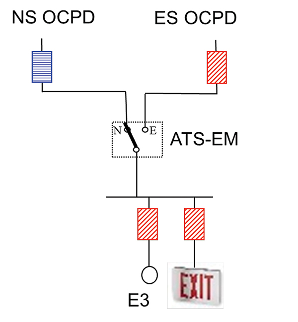
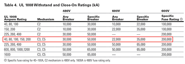
Let’s assume a basis of design utilizes an Eaton ATC-300 Series transfer switch. The normal source OCPD is a 100 A Eaton Bussmann™ series Low-Peak™ LPJ (Class J) fuse. The emergency source OCPD however is integral with the generator and the generator manufacturer has selected a 100 A Eaton HFD circuit breaker. Referring to the manufacturer’s documentation shown in Figure 4, the Eaton ATC-300, C3 has a rating of 200,000 A with the 100 A Low-Peak LPJ (Class J) fuse but only a 50,000 A rating with the Eaton HFD circuit breaker (which is listed in the acceptable specific circuit breaker list not shown). To comply with NEC 110.3(B) and 110.10, the short-circuit (fault) current from the normal source cannot exceed 200,000 A and the short-circuit (fault) current from the emergency source cannot exceed 50,000 A.
However, if for some reason the project deviates from the basis of design, there can be a negative impact to the suitability of the transfer switch. For instance, if the Class J fuse was changed to a circuit breaker, the SCCR of the transfer switch would be reduced from 200 kA to 30-50 kA depending upon the circuit breaker used. If the short-circuit (fault) current is above this new value, the transfer switch size would need to be increased. For instance, if the short-circuit (fault) current was 65,000 A, the transfer switch would have to be increased from 100 A to 600 A with the specific circuit breaker required to achieve this rating.
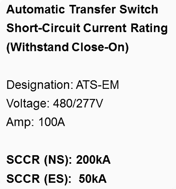
A field installed label, similar to Figure 5, would need to be installed per NEC 700.5(E). Currently the 2017 NEC does not require documentation or labeling of the short-circuit (fault) current as required for other equipment types such as service equipment, industrial control panels, HVAC equipment, industrial machinery or elevator controllers. However, in order to verify compliance to 110.10, the electrical inspector should ask the installer to verify the available bolted three-phase short-circuit (fault) current from both the normal and emergency source. In this example, it is not likely the short-circuit (fault) current exceeds the SCCR of the transfer switch as protected.
Summary
The SCCR for transfer switches can be confusing for electrical engineers, installers and inspectors. This is due to the fact that there is typically not just one single SCCR for transfer switches. Rather, the transfer switch SCCR depends upon the specific type and characteristics of the OCPD that is protecting it.. The design engineer has the option to select a specific circuit breaker, any circuit breaker with a specified clearing time or a current-limiting fuse. Transfer switches can have optional short-time current ratings where circuit breakers without instantaneous trips are needed for compliance with selective coordination requirements in the NEC. Transfer switches typically have high SCCR levels with current-limiting fuses, medium SCCR levels with circuit breakers that depend upon the interrupting rating and clearing time of the circuit breaker, and lower SCCR levels with circuit breakers without an instantaneous trip. Proper selection of the transfer switch and field labeling the specific SCCR of the transfer switch based on the actual installation is required for compliance with the 2017 NEC.