One of the most versatile components of an electrical raceway system is the conduit body. The National Electrical Code defines a conduit body as “A separate portion of a conduit or tubing system that provides access through a removable cover(s) to the interior of the system at a junction of two or more sections of the system or at a terminal point of the system. Boxes such as FS and FD or larger cast or sheet metal boxes are not classified as conduit bodies.” This definition, however, doesn’t fully describe all of the uses permitted for a conduit body in the NEC, as a conduit or cable fitting, a splice box, a device box, a junction box and a pull box.
Knowing the exact use for which the conduit body will be employed is critical in applying the appropriate sections of the NEC.
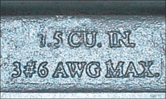
Photo 1. Internal volume marking required by NEC 314.16 in the conduit body
General
First and foremost, a conduit body is part of the raceway system to which it is attached. A listed conduit body is always subject to the construction and performance requirements for a conduit fitting for direct attachment to conduit or tubing. In addition, it is anticipated that a conduit body will be used as a pull box, and therefore they are subject to either specific dimensional or performance requirements to ensure adherence to wire fill requirements and protection for electrical conductors during pulling according to NEC 314.28.
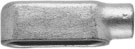
Photo 2. Simple conduit body
Metallic conduit bodies are provided with means for securing rigid or intermediate metal conduit by threading into internally threaded hubs or electrical metallic tubing (EMT) by unthreaded hubs having set-screws. Nonmetallic conduit bodies may have unthreaded hubs (sockets) into which rigid PVC conduit is to be glued or internally threaded hubs to accept threaded adapters that are listed for use with raceways. It has also been common practice to connect a wide variety of approved raceways, cables and cord to internally threaded hubs in conduit bodies using listed fittings.
Conduit Bodies Used As a Box for Housing Splices or Wiring Devices
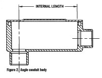
Figure 2. Angle conduit body
NEC 300.15 also recognizes a conduit body as equivalent to a box for containing wire splices and wiring devices, such as a switch or receptacle. When intended for such use, a conduit body is subject to the requirements for a box. The simplest way to determine if a listed conduit body is suitable for use as a splice box or as an outlet or device box is to look for the internal volume marking required by NEC 314.16 in the conduit body. These same rules apply for determining the minimum size of the conduit body used as a box. Since a conduit body does not typically contain screw holes for wiring device mounting, specially designed and listed covers, for this purpose, are provided by the manufacturer of the conduit body. According to NEC 314.5, “Conduit bodies such as capped elbows and service-entrance elbows that enclose conductors 6 AWG or smaller, and are only intended to enable installation of the raceway and the contained conductors, shall not contain splices, taps, or devices and shall be of sufficient size to provide free space for all conductors enclosed in the conduit body.”
Conduit Body Configurations
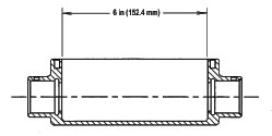
Figure 3. Example largest hub size 21 (3/4): Measurements expressed as multiples of trade sizes are to be determined by converting the trade size of the raceway (not the metric designator) to a value expressed in millimeters.
The simplest conduit body has only one raceway attachment hub. The obvious use for this conduit body is at a termination point of a wiring system. These conduit bodies typically are designed to contain wire splices or a wiring device so most often they will be listed for this purpose. Be sure, however, to look for the internal volume marked in the conduit body for verification.
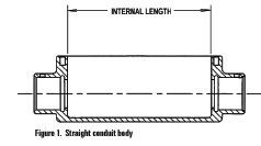
Other conduit body configurations may have two, three or even four raceway attachment hubs of the same size or different sizes. Two hub configurations are often referred to as straight, LB, or LL or LR, to designate the direction the raceway will be diverted [straight—straight through end-to-end; LB—90 degrees through the back of the body opposite the cover; LL or LR—90 degrees through the left or right side of the body]. Three hub configurations are referred to as “T” bodies, and four hub configurations as “X” bodies (see photo 3).
Minimum Size of Conduit Bodies Used as Pull and Junction Boxes
NEC 314.28 establishes certain minimum dimensions for pull and junction boxes and conduit bodies to ensure adherence to wire fill requirements and protection for electrical conductors during pulling. Conduit bodies of dimensions less than those required by 314.28(A)(1) and (A)(2) are permitted under conditions specified in 314.28(A)(3).
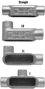
Photo 3. Conduit body configurations can have two, three or even four raceway attachment hubs of the same size or different sizes.
Understanding and enforcement of the requirements in Section 314.28 are sometimes difficult. In particular, since many of the conduit bodies offered today take advantage of the “smaller dimensions” provision in 314.28(A)(3), verifying the minimum and maximum size and number of conductors for which a conduit body is acceptable can be a challenge. Listed conduit bodies have been evaluated for their compliance with these minimum dimensions or exceptions, and required markings. The following is intended to provide some clarity to the requirements in NEC 314.28.
314.28(A) Minimum Size. The smallest size conduit or tubing hub provided in a conduit body is metric designator 16 (trade size 1/2). Since only one 4 AWG conductor consumes the maximum wire fill for 16 (1/2) conduit or tubing, conduit bodies having only 16 (1/2) size hubs are exempt from the requirements in 314.28. Section 314.5 applies to such conduit bodies. The requirements in 314.28, therefore, apply to conduit bodies having hub sizes 21 (3/4) or larger.
The so-called “6 and 8 times rule” addressed in 314.-28(A)(1) and (A)(2) respectively, establishes a seemingly simple guide for determining adequate space between entry hubs and walls and entry and exit hubs for through pulls. Since through pulls generally require bending of the conductors or cables, adequate space to accommodate the pulling operation, without over-bending, is an important and required design consideration.
Although traditional trade sizes (3/4, 1, 1-1/4, etc.) for conduit and tubing have always been nominal (not representing actual inch dimensions), their use as the “units of measure” in inches has been prevalent, representing the conduit or tubing diameter for the purpose of calculating the required length according to the 6 and 8 times rule. The metric designators [NEC Table 300.1(C)] now the preferred reference in the NEC, if applied in millimeters as the “units of measure employed,” would require a greater length than that calculated using the traditional trade size/inch as the “units of measure employed.” The examples in figures 3 and 4 demonstrate the recommended conversion where SI metric conversion is desirable (1 inch = 25.4 mm).
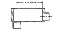
Figure 4. Example largest hub size 21 (3/4): Measurements expressed as multiples of trade sizes are to be determined by converting the trade size of the raceway (not the metric designator) to a value expressed in millimeters.
Since cable wiring systems can only be connected to conduit bodies by use of listed cable fittings designed to thread into standard trade size threaded conduit entries, special care needs to be taken when transposing cable size into raceway size for these dimensional calculations. Present cable designs are often able to provide larger conductors in cable assemblies having significantly reduced outside diameters. The conduit body hub size into which listed fittings for these smaller cables are able to be assembled may not represent the minimum metric designator (trade size) raceway required for the number and size of conductors in the cable. The minimum metric designator (trade size) raceway used for this calculation shall be based on Table 1, Chapter 9.
(1) Straight Pulls. The length of the conduit body shall not be less than eight times the metric designator (trade size) of the hub that will accommodate the largest raceway.
(2) Angle or U Pulls (Conduit body configurations LB, LL, LR, T). The distance between each raceway entry inside the conduit body and the opposite wall of the box shall not be less than six times the metric designator (trade size) of the largest raceway. This dimension is not applicable when the opposite wall is the removable cover.
(3) Smaller Dimensions. Since many of the conduit bodies offered today take advantage of the “smaller dimensions” provision in 314.28(A)(3), verifying the maximum size and number of conductors for which a conduit body is acceptable, can be a challenge.
UL 514B, Conduit, Tubing and Cable Fittings, contains the requirements for listed conduit bodies. For conduit bodies designed to take advantage of this “smaller dimensions” provision, the manufacturer must specify the maximum size conductor and the number of conductors of that size, and the conduit bodies are then subjected to a wire pull test to ensure damage to the conductors does not occur. If wire pulling lubricant is specified by the manufacturer for use during the test, this must be provided as a marking on the product.
The marking requirement indicating the maximum size conductor for which the “smaller dimension” conduit body has been found acceptable is straightforward. And, the maximum number of the same size maximum conductor can also be clearly indicated in the marking. Particularly in larger size conduit bodies, however, often more than one size conductor is pulled into a conduit body and it is not always clear by the manufacturer’s markings what combinations of conductors are included in the conduit body listing. The only sure way to make this determination is to utilize the same method as one would to calculate the conductor fill in a conduit where various size conductors will be installed (see NEC chapter 9 tables). Since the conduit body manufacturer clearly provides the marking of the maximum size conductor and the maximum number of that conductor, one is able to calculate the percentage wire fill represented for the smallest conduit body hub size in a through run. Any additional combinations of conductor sizes must comply with that calculated conduit wire fill percentage for that size conduit.
Conduit Bodies in Damp and Wet Locations
NEC 314.15(A) provides the requirements for conduit bodies installed in damp and wet locations. Although gasketed covers are generally provided for use with conduit bodies, this does not necessarily mean that all conduit bodies are suitable for use in damp or wet locations. Listed conduit bodies are required to be marked “For use in wet locations” or “Wet locations” where determined by test to be suitable for this application. Field assemblies of conduit bodies with listed conduit or cable fittings threaded into conduit body hubs have not typically been evaluated for use in wet locations as part of their listing. Conduit and cable fittings listed and marked for use in wet locations, similarly have not typically been listed for such use when field assembled into the threaded hubs of a conduit body.
Support of Conduit Bodies
Conduit bodies are permitted to be supported by rigid and intermediate metal conduit, EMT, and rigid nonmetallic conduit, as appropriate, in accordance with the exceptions in NEC 314.23 (E) and (F).
Conduit Body Covers
All conduit bodies are required to be provided with compatible covers that are suitable for the conditions of use. Because of industry standardization, covers are not always shipped from the factory with assemblies that include covers and/or gaskets. In dry locations, the covers and conduit bodies of different manufacturers are generally interchangeable. For wet locations, however, a conduit body and a cover specified by the listed manufacturer is required to be used.