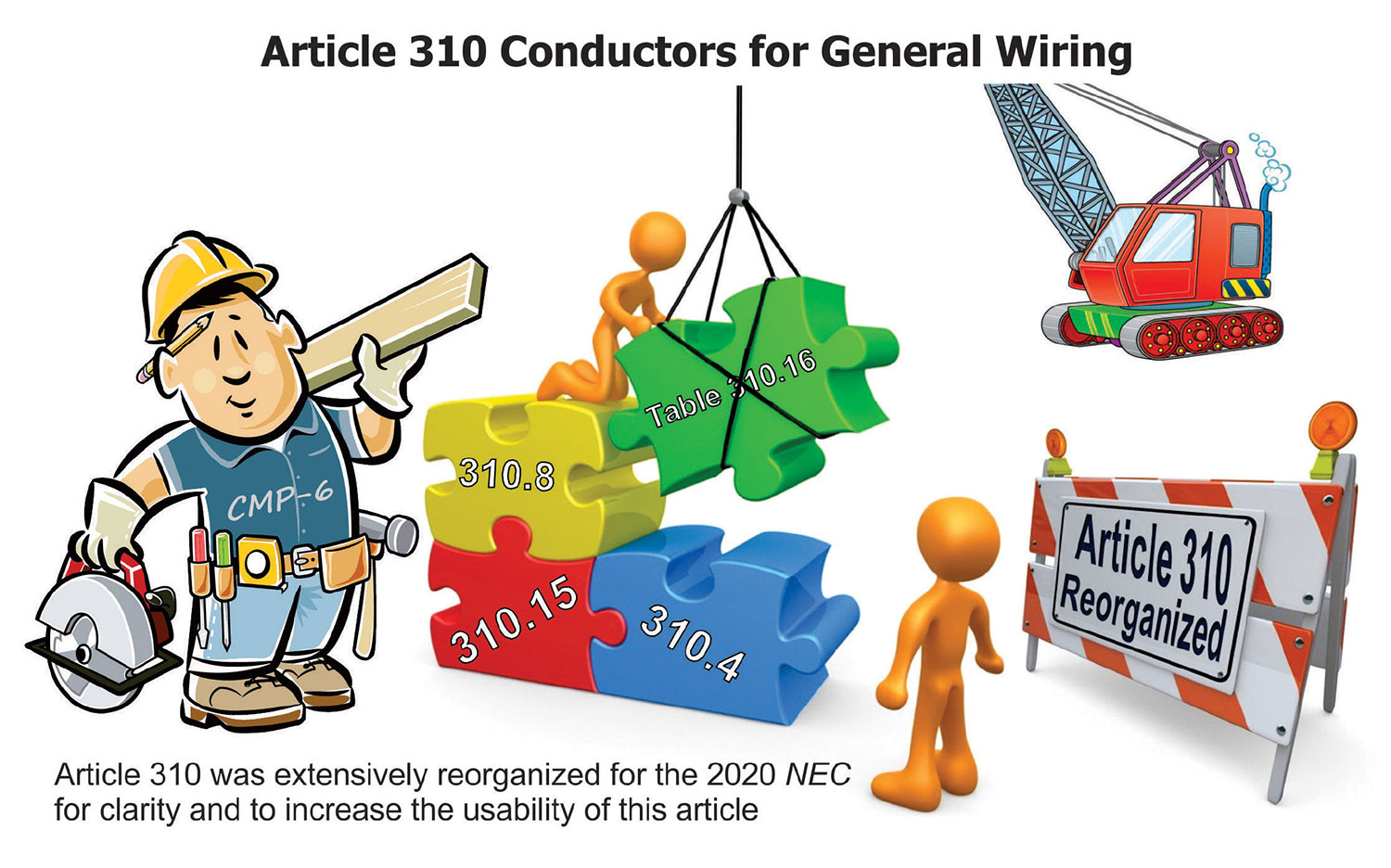
As indicated by the scope of Article 310, this article covers general requirements for conductors rated up to and including 2000 volts and their type designations, insulations, markings, mechanical strengths, ampacity ratings, and uses. This article on conductors has been a part of the Code since the 1947 NEC. Article 310 has been extensive reorganization to increase the usability of the article for the 2020 NEC. The ampacity requirements over several Code cycles have become increasingly difficult to use, which in turn made Article 310 more difficult to use. Great effort was made by Code Making Panel (CMP) 6 only to change the organization and not rewrite NEC text wherever possible. Text was extracted and moved for clarity, with some redundant text deleted. In this writing, we will take a look at some of the more substantial changes to Article 310 for the 2020 NEC.
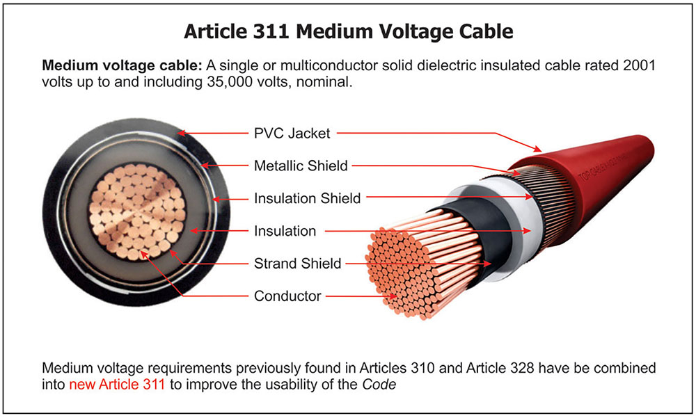
Article 311 — Medium Voltage Cable
One of the more significant changes to Article 310 was to remove all references to medium voltage (Type MV) conductors and cables and place these requirements in a new Article 311. This new article also includes moving the Type MV cable requirements out of previous Article 328 and deleting that article entirely. This article will cover the use, installation, construction specifications, and ampacities for medium voltage conductors and cables. This was an effort in part to increase the usability of Article 310 by leaving only the general requirements for conductors rated up to and including 2000 volts. This work resulted in separating the 0 to 2000-volt requirements (Article 310) from the medium voltage requirements (Article 311), which should go a long way in resolving the usability issues with medium voltage conductors and cables.
Medium voltage cable is defined as “a single or multiconductor solid dielectric insulated cable rated 2001 volts up to and including 35,000 volts, nominal.” The requirements of this new article do not apply to conductors that form an integral part of the equipment, such as motors, motor controllers, and similar equipment, or to conductors specifically provided for elsewhere in the NEC.
Prior to this new article, it was difficult to gather all necessary information pertaining to Type MV conductors and cables as they were scattered within the Article 310 ampacity tables for cables up to 2000 volts. Type MV conductors and cables had installation requirements in eight different locations of Article 310, and nine requirements were found in Article 328. Requirements for medium voltage conductors and cables (rated 2001 volts through 35,000 volts) were introduced to Article 310 during the 1975 NEC, and a new article titled “Medium Voltage Cable” (then Article 326, later Article 328) was added to the 1978 NEC. Since then, additional medium voltage installation requirements have been intermingled through Article 310 and requirements added to Article 328. This has created unnecessary effort to find all NEC requirements for Type MV cable.
Article 310 Ampacity Tables
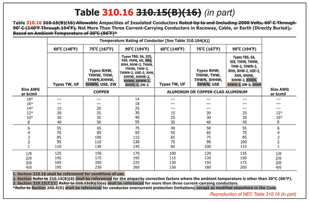
For a number of Code cycles, the most used table in the entire NEC was simply referred to as Table 310.16 [rather than Table 310.16(B)(16) as it was known as for the 2011 NEC through the 2017 NEC]. Article 310 (Conductors for General Wiring) went through an extensive reorganization for the 2011 NEC Code cycle. This reorganization had an extreme impact on the tables within the article as every table within Article 310 was renamed for the 2011 NEC. This was an effort to bring the table numbering in line with the NEC Style Manual, in particular section 2.3.1, which states, “Tables and figures shall be referenced in the text and shall be designated by the number of the NEC rule in which they are referenced.” Proposals were submitted and accepted to correlate all the references to their tables throughout the Code. For the 310.15(B) tables, proposals were submitted to name these tables simply Table 310.15(B)(1) through 310.15(B)(6), but CMP-6 selected table numbers 310.15(B)(16) through 310.15(B)(21) to somewhat match the existing table numbers and improve usability.
As stated earlier, Article 310 was heavily revised and reorganized for the 2020 NEC, which resulted in the ampacity tables of Article 310 being renamed once again. Great care was taken to renumber the sections referencing the ampacity tables by the numbering matching the previous table numbering system. As a result, the ampacity tables in Article 310 will simply be titled as Table 310.16 through Table 310.21. As an example, Former Table 310.15(B)(16) will revert to its original numbering and simply be known as Table 310.16. New sections were added at 310.16 through 310.21 that now refer to the ampacity tables and contain conditions of use previously found in the table headings. The ampacity table headings were shortened, and a note referring to the section language was added to each table. All of the notes to the tables were retained at the bottom of the ampacity tables.
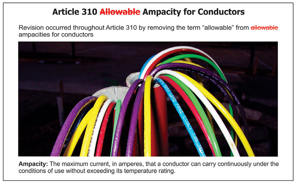
“Allowable” Ampacities for Conductors
As part of the reorganization and revision of Article 310 for the 2020 NEC, the word “allowable” as in allowable ampacity was removed from Article 310 thirteen times throughout the article. This revision was the result of the work of an Ampacity Task Group formed by the NEC Correlating Committee. Regarding the ampacity of a conductor, “Ampacity” is defined in Article 100 as “the maximum current, in amperes, that a conductor can carry continuously under the conditions of use without exceeding its temperature rating.” The Ampacity Task Group determined that the proper term used throughout Article 310 should be “ampacity” and not “allowable ampacity.” This section intends to determine the ampacity of the conductor based upon its condition of use. The use of the word “allowable” did not add any clarity and was deleted in several locations.
Uses Permitted for Type XHHN, XHWN, and XHWN-2 Conductors
During the revision cycle for the 2017 NEC, three types of conductor insulations were recognized by the Code at Table 310.104(A) [now Table 310.4(A)]. Those conductor insulation types were XHHN, XHWN, and XHWN-2 type conductors. An XHHN type conductor is a cross-linked synthetic polymer insulation, 90°C (194°C) maximum operating temperature, outer nylon jacketed (or equivalent) conductor that can be used in a dry or damp location. The letter type designation XHWN denotes a cross-linked synthetic polymer insulation, 75°C (167°C) maximum operating temperature, moisture resistant, outer nylon jacketed (or equivalent) conductor that can be used in a dry or wet location. A conductor with the letter type designation of XHWN-2 means it is suitable for use in dry locations up to 90°C (194°F), or wet locations up to 75°C (167°F) with the conductor being a cross-linked synthetic polymer insulation, moisture resistant, outer nylon jacketed (or equivalent) conductor. Prior to the 2017 NEC, only thermoplastic insulation with a nylon jacket was allowed by 310.104 and Table 310.104(A). With the acceptance of Type XHWN and XHWN-2 conductors, thermoset insulation with a nylon covering was acceptable.
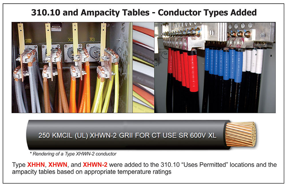
Even though these conductor types were recognized by Table 310.104(A) (Conductor Applications and Insulations Rated 600 Volts) in the 2017 NEC, they were inadvertently left out of the Article 310 ampacity tables. The 2020 NEC rectified this omission. Type XHHN, XHWN, and XHWN-2 insulated conductors were added to the insulated conductors and cables that can be used in dry and damp locations at 310.10(B), and XHWN, XHWN-2 type conductors were added to the insulated conductors and cables that can be used in wet locations at 310.10(C). At the ampacity tables, Type XHHN, XHWN, and XHWN-2 insulated conductors were added to the 90°C (194°F) columns of Tables 310.16, 310.17, and 310.20. Type XHWN insulated conductors were added to the 75°C (167°F) columns of these same ampacity tables.
A similar change occurred at 310.3(B) [was 310.106(B)]. Part of this section identifies the conductor types acceptable for stranded aluminum conductors 8 AWG through 1000 kcmil. Type XHHN and XHWN were added permitted to aluminum conductors along with conductors marked as Type RHH, RHW, XHHW, THW, THHW, THWN, THHN, service-entrance Type SE Style U, and SE Style R. These aluminum conductors must be made of an AA-8000 series electrical grade aluminum alloy conductor material.
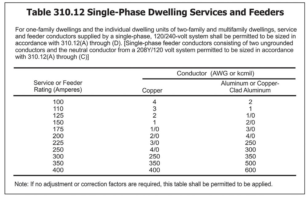
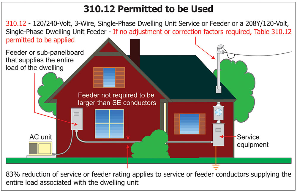
Single-Phase Dwelling Services and Feeders
For the 2020 NEC, a new dwelling unit service ampacity table was added at 310.12, and text added indicating table permitted to be used if there are no temperature correction or adjustment factors needed. This dwelling unit ampacity table has a rich and long history with the NEC.
From the publication of the 1956 NEC, residential service-entrance conductors have been permitted to be sized at a slightly higher ampacity values than the normal ampacity values found in the ampacity tables such as Table 310.16 or some form thereof in previous editions of the Code. This higher ampacity allowance was permitted primarily due to the diversity loads associated with dwelling units. The genesis of new 310.12 (and new Table 310.12) can be traced to a note at the bottom of Table 1a of Chapter 10 of the 1956 NEC. In the 1959 NEC, this ampacity table and its associated notes were moved to Table 310-14. This provision stayed pretty much the same until the 1971 NEC when this ampacity table became Table 310-12, and the note became specific to 3-wire, single-phase “residential” services. In the 1975 NEC, this residential service ampacity provision became “Note 3 to Table 310-16 through 310-19” titled, “Three-Wire Single-Phase Residential Services.” The residential ampacity values first appeared in a table format in the 1978 NEC as a table under Note 3 to Tables 310-16 through 310-19. The 1978 NEC was where feeder conductors were first introduced to this residential ampacity value provision as well. This provision stayed basically the same until the 1993 NEC where feeder conductors utilizing this note were limited to “feeder conductors that supply the total load to a dwelling unit…” The 1999 NEC witnessed this residential ampacity provision moved to from a note to its own subsection at 310-15(b)(6) and Table 310-15(b)(6) and then to 310.15(B)(7) in the 2011 NEC.
This decades-old table was removed from the Code in the2014 NEC and replaced with an ampacity reduction of not less than 83 percent of the service or feeder rating of the ampacity values of then Table 310.15(B)(16). This 0.83 multiplier resulted in basically the same ampacity values of previous Table 310.15(B)(7) (which was removed). This dwelling unit ampacity table was reintroduced to the Code for the 2017 NEC, but it was located in Informational Annex D, following Example D7. The table was added to show the correct dwelling unit service or feeder conductor sizes required if there are no adjustment or correction factors that must be applied. Again, the conductor sizes shown in this table correspond to the 83 percent allowance permitted by the provisions of 310.15(B)(7) [now 310.12(A) and (B)] for dwelling unit service and feeder conductors.
To come full circle, this dwelling unit ampacity table makes a triumphant return to the Code for the 2020 NEC. Locating this table in Article 310 will make this table enforceable (as compared to informative in Annex D) and give the user of the Code the option to size these dwelling unit service or feeder conductors per this table when no conductor correction or adjustment are needed. This change was an effort to make the Code more user-friendly. For ease of use, putting this sixty-five-year-old table back in Article 310 makes sense and compliments the reorganization of Article 310 for the 2020 NEC revision cycle.
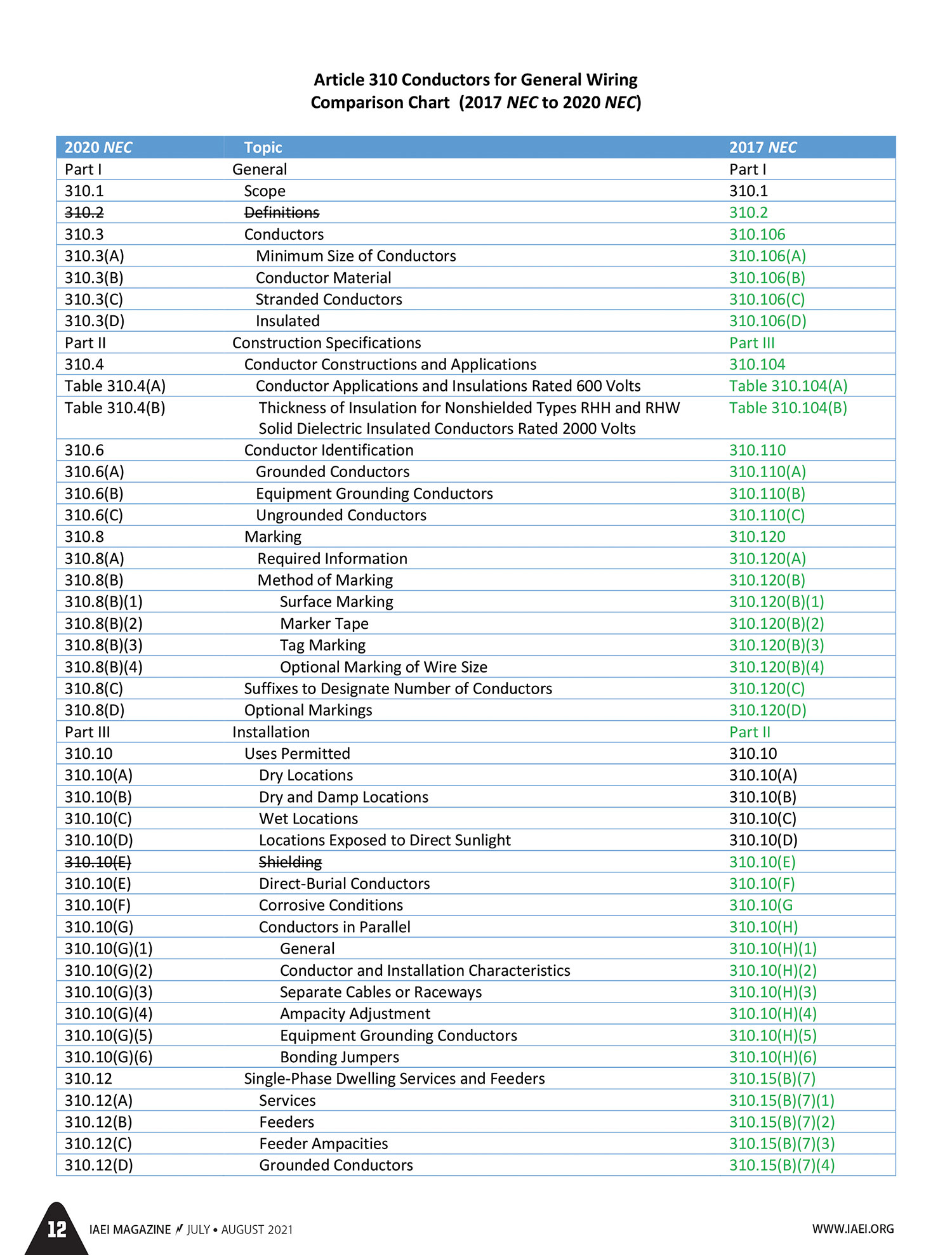
Conclusion
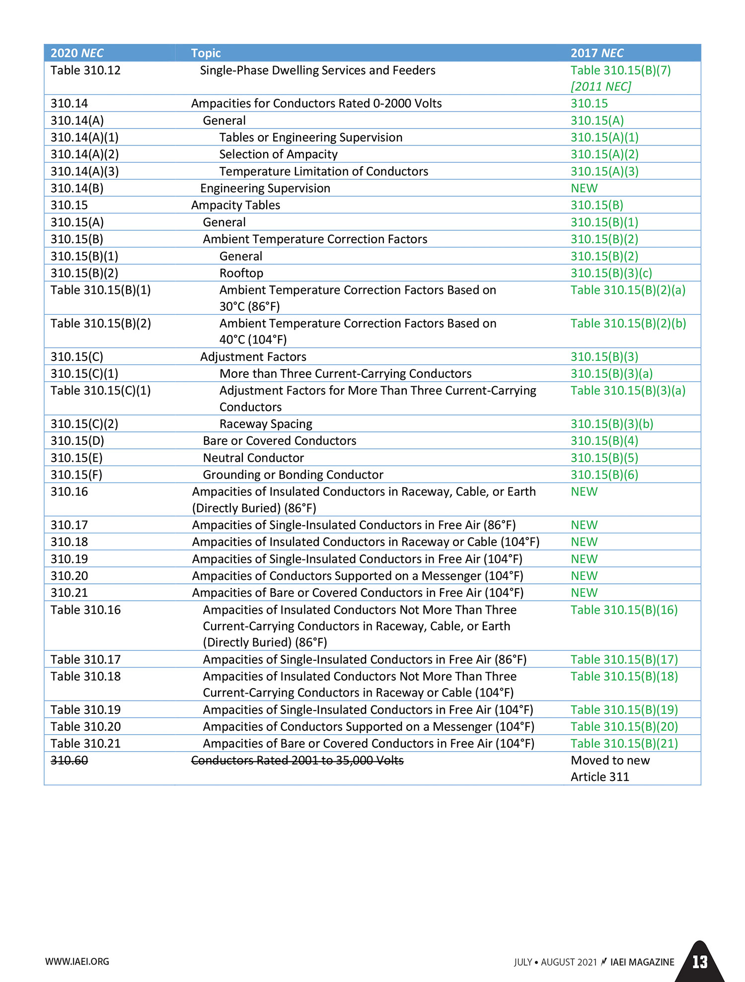
From time to time, it becomes necessary to reorganize an article of the NEC. Over a few Code revision cycles, changes are made, and requirements are added to a particular article. Before you know it, you have to go to different places within an article to find common requirements such as grounding and bonding or securing and supporting requirements. For the 2020 NEC, CMP-6 recognized that it was time to reorganize Article 310 and create a new Article 311 for medium voltage conductors and cables. Again, this was an effort to make the Code more user-friendly for the user of the Code. For the convenience of our readers, IAEI has put together a comparison chart comparing Code references and the requirements of Article 310 for the 2017 NEC versus the Article 310 Code references for the 2020 NEC.