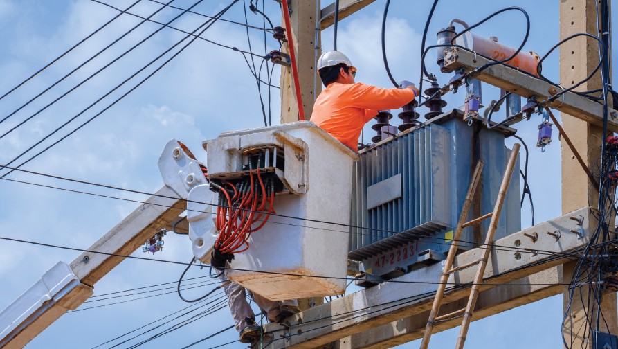
The conductor temperature is a critical part of the design, construction, and checking clearances of aerial electric supply lines.
Line Design
In my article on “Overhead Line Design From Scratch – Part 1″ in the March/April 1998 issue of IAEI News, I discussed conductor choice based upon steady-state ampacity, transient ampacity, short-time ampacity, voltage drop, sag/tension characteristics, cost and losses. The ampacity of the conductor is a function of the conductor’s physical properties, conductor maximum operating temperature and ambient weather conditions, including air temperature, wind velocity and solar intensity. For insulated conductors, the maximum operating temperature is the maximum temperature of the insulation material. For bare conductors, the maximum operating temperature is chosen by the designer of the aerial electric supply line.
How high can we go? Economics limit the conductor temperature well below the temperatures that can actually damage the conductor. As the conductor temperature increases, the sag increases. The sag increase requires us to use taller structures or more structures to maintain good clearances. Both increase the cost of the line. As the conductor temperature increases, the resistance of the wire increases. The resulting increase causes greater voltage drop and higher losses. If we set the maximum operating temperature too low, we end up using a much larger and more expensive conductor than necessary. 212° F. is commonly chosen. Once we choose a maximum operating temperature and design the line based upon that temperature, we must make sure the operating personnel do not allow the design ampacity to be exceeded.
An industrial plant manager once asked me the ampacity of the 12kV lines that feed the various buildings in the industrial complex. The lines had been designed and constructed by a consultant about twenty years before his request. There was no record of the ampacity/maximum operating temperature used to design the line. We measured the ground clearances and conductor sags for several of the longest spans. We also measured the conductor temperatures. We calculated the conductor tension and plugged it into a sag/tension computer program to determine sags at various high temperatures. Since we measured conductor heights above ground at the points of attachment on the structures, we calculated the maximum conductor sags, which would comply with the NESC® requirements. The plant manager was not happy to find out the line was constructed for a maximum operating temperature of 130° F. and that they were already exceeding the ampacity of the line. The line was in violation of the NESC® requirements. The line was probably field designed.
Line Construction
Once we decide what maximum operating temperature we will use to design the line, we then have to determine the stringing sag/tension we will use to construct the line. As discussed in my March/April 1998 article, we get the sag/tension stringing details from the sag/tension computer program. The temperatures listed by the program are conductor temperatures, not air temperature. On a hot sunny day, it is not uncommon for a conductor not carrying any current to be 50 degrees hotter than the air temperature. The line crew installing and tensioning the conductors must be given the sag/tension details from the computer program and must have an accurate way of measuring the conductor temperature at the time of tensioning. I give our construction personnel a graph of stringing sag in inches versus conductor temperature so they can pick off the appropriate sag for their conductor temperature.
Conductor Temperature Measurement
Hand-held electronic thermometers with surface probes work very well for measuring the temperature of “dead” conductors like during the stringing process. When we are checking the clearance of an existing energized line as discussed in my July/August and September/October 1999 articles, measuring the conductor temperature is much more difficult. The electronics of most thermocouple type electronic thermometers don’t like high voltage. The devices turn off when the energized wire is contacted. I understand that some thermistor-type electronic thermometers have the same problem. The device I use is a thermistor type and is no longer available. I’m working with two manufacturers to find a device that will work. When I find a production device that works, I will let you know. Most infrared thermometers don’t work because the target diameter is too large. For clearance measurement, we want to be able to measure the conductor temperature from the ground. The device I use is mounted on a “V” shaped guide on the end of a 50-foot fiberglass extension pole (the same pole I use to measure vertical clearances). The probe is mounted at the bottom of the “V” so that the probe doesn’t miss the conductor. An electronic thermometer with a “peak” function is necessary so that you can recall the conductor temperature after you lower the device to the ground.
The Alternative
As discussed in my March/April 1998 article; IEEE® Standard 738-1993 is one source that can be utilized to determine the ampacity of bare conductors. The calculation method presented in the standard and the associated computer program (included with the standard) can also be used to predict the conductor temperature given the conductor’s physical properties, current flow in the conductor and weather conditions. The results are only as accurate as the input data. The input data consists of thirteen variables, which are not easy to measure.
1. Air temperature
2. Wind speed
3. Angle between the wind direction and the conductor
4. Altitude of the conductor above sea level
5. Direction of the conductor relative to a compass
6. Latitude of the conductor
7. Sun time
8. Visibility
9. Conductor diameter
10. Conductor resistance at 25° and 75° C.
11. Conductor emissivity
12. Conductor absorptivity
13. Current flow in the conductor
Each of the variables is explained in detail in the standard. To complicate matters, each variable is considered by the program to be constant. The field conditions are not constant. Variations in air temperature, wind speed, wind direction, visibility and current flow all affect the results. For that reason, the program can only be used to roughly predict the conductor temperature.
Conclusion
There is no substitute for actual measurement of the conductor temperature.
If you have enjoyed this article or have general questions about the NESC®, please call me at 302-454-4910 or e-mail me at dave.young@conectiv.com.
National Electrical Safety Code®, NESC® and IEEE® are registered trademarks of the Institute of Electrical and Electronics Engineers.


Find Us on Socials