Overcurrent protection for motors and motor circuits is a little different than the rules for conductors as specified in Article 240, because motor loads have different characteristics than general lighting and other loads. Motor circuits draw a large amount of current at initial start-up, usually around six times the normal full-load current (FLA) of the motor. This large amount of current drawn at start-up is usually referred as the “inrush current,” although the Code term is “locked rotor current” (LRA) (see Figure 1).
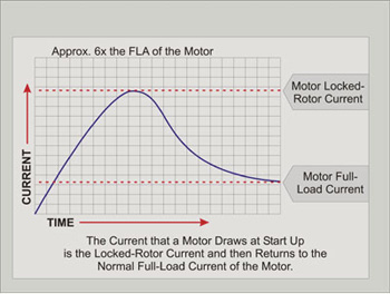
Figure 1. This large amount of current drawn at start-up is usually referred as the “inrush current,” although the Code term is “locked rotor current” (LRA)
Safe wiring installations of electric motors and motor circuits depend on the proper understanding and application of some basic requirements in Article 430 of the National Electrical Code, particularly those in Section 430-6 for general motor installations or inspections. Instead of the nameplate full-load current, Section 430-6 requires the tables in Article 430 to be used to size circuit conductors, branch-circuit short-circuit and ground-fault protective devices, and ampere ratings of disconnect switches (see Figure 2). The actual full load current for different motors of the same size and type may vary. The tables are used to ensure that if a motor needs to be replaced, the components of the motor circuit will not also need to be replaced. This requirement applies to general motor applications. The rules for torque motors and alternating-current adjustable voltage motors are different. The actual nameplate current is used to size these components of the circuit. This article deals with general motor applications.
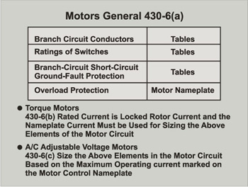
Figure 2. Instead of the nameplate full-load current, Section 430-6 requires the tables in Article 430 to be used to size circuit conductors, branch-circuit short-circuit and ground-fault protective devices, and ampere ratings of disconnect switches
When installing or inspecting a motor circuit for the proper overcurrent protection, a systematic approach usually works best. The four elements of the installation typically examined include, (1) the branch-circuit sizing (conductors), (2) the overload protection, (3) the branch-circuit short-circuit ground-fault protective device, and (4) the rating of the motor disconnect (see Figure 3). These four elements are the major items of concern in the installation or inspection and certainly are not all-inclusive as installations differ.
The motor nameplate information is important. The nameplate voltage and horsepower ratings are needed in order to use the tables in Article 430. The horsepower rating at the applied voltage is used with the appropriate table to determine the full-load current rating of the motor. This full-load current value must be used to size the conductors and the branch-circuit short-circuit and ground-fault protective device.
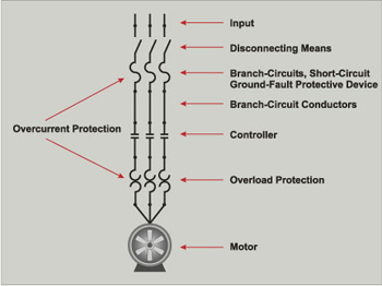
Figure 3.
Motor Branch-Circuit Conductor Sizing
As an example, a 115-volt, 1½ horsepower electric motor draws 20 amperes based on Table 430-148. Even though the motor nameplate (see Figures 4, 5, and 6) indicates it draws 18.6 amperes at 115 volts, the value in Table 430-148 must be used for sizing purposes, as required by Section 430-6(a).
The next component of the motor circuit is the branch-circuit conductor sizing. Part B of Article 430 covers the requirements for sizing the branch-circuit conductors for single motors and groups of motors. This is a single motor example, so looking at Section 430-22(a), a single motor used in a continuous duty application (three hours or more) is required to have an ampacity of not less than 125% of the motor full-load current as determined by Section 430-6(a)(1). Taking the value of 18.6 amperes and multiplying it by 125% results in an ampere value of 23.5 amperes. The minimum conductor size for this motor circuit, after any ampacity adjustments or correction factors have been applied, would need to be a minimum of 23.5 amperes. Using Table 310-16, the Code permits No. 12 THWN copper conductors for this installation, which would permit some cable assemblies, such as Type NM and others sized at No. 12, to be used for this application. There are other factors that can contribute to the size of the motor branch-circuit conductors, such as voltage drop in long runs and the application of ampacity adjustment factors for either number of current-carrying conductors in the same raceway or ambient temperature adjustment or both.
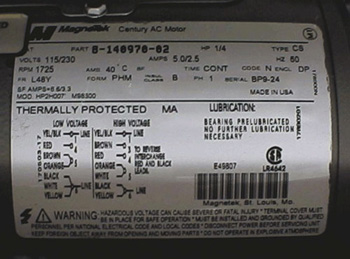
Photo 1. Thermaly protected motor
Motor Branch-Circuit Short-Circuit and Ground-Fault Protection
Branch-circuit short-circuit and ground-fault protective devices are required to be sized in accordance with the values given in Table 430-148 also. The branch-circuit short-circuit ground-fault device sizing requirements are located in Part D of Article 430. In Section 430-51 the Code says that these rules included in Part D amend or add to the requirements of Article 240. A few different types of branch-circuit short-circuit and ground-fault protective devices may be used for protecting motor branch-circuit conductors, motor control apparatus, and the motor against overcurrent due to short-circuits or grounds. Section 430-52(c) requires that the rating of the protective device that is used must not exceed the value calculated according to the percentage values given in Table 430-152. A look at Table 430-152 for a single- phase motor allows the following percentages.
• Nontime Delay Fuse 300%
• Dual Element Time-Delay Fuse 175%
• Instantaneous Trip Circuit Breaker 800%
• Inverse Time Circuit Breaker 250%
Basically these increases in percentages are to allow the motor to be started without causing the device to trip at locked rotor (starting) current. Where the values determined by the percentages in Table 430-152 do not correspond to the standard sizes or ratings of fuses, nonadjustable circuit breakers, or possible settings of adjustable circuit breakers, the next standard size, rating, or possible setting is permitted. The idea here is to provide a device that will afford the short-circuit and ground-fault protection and still be large enough to allow for the inrush current (locked rotor current) when the motor starts. If the motor locked rotor current is still great enough to trip the device at start-up, the percentage values given in Table 430-152 are again allowed to be increased to the maximum values given in the Exception No. 2 (a), (b), (c), and (d).
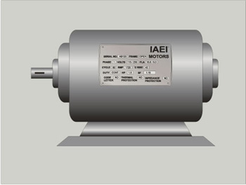
Figure 4.
Using a nontime delay fuse as the short-circuit ground-fault protective device for the 1½ horsepower, 115-volt motor, the device would be required to be sized at a maximum using the value 18.6 and multiplying that value by 300%, which results in a device rated at 55.8. Rounding up to the next higher standard size as permitted by Section 430-52(c)(1) Ex. No. 1, the short-circuit ground-fault protective device could be a 60 ampere nontime delay fuse and be in compliance with Section 430-52. This might appear as though the No. 12 conductors installed for the branch-circuit conductors would be unprotected. Remember, the rules in Part D of 430 amend the rules in 240 at this point. Do not expect the conductor to be protected at its ampacity, as it would be normally in Article 240.
There is still another level of protection to be provided in the motor circuit that completes the overcurrent protection for the motor and the motor circuit.
Motor and Branch-Circuit Overload Protection
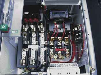
Photo 2. Thermal heaters in a magnetic motor starter
Overload protection devices are intended to protect motors, motor-control apparatus, and motor branch-circuit conductors against excessive heating due to motor overloads and failure to start. An overload in an electrical motor circuit is an operating current that, if it persists for a sufficient length of time, would cause damage or dangerous overheating of the apparatus. Overload protection does not include protection against short-circuits or ground-faults. The combination of the overload protective device and the branch-circuit short-circuit ground-fault protective device provide the overcurrent protection for the motor and motor circuit.
Overload protection for motors can be provided in a few different forms. If the motor itself is a thermally protected motor, it is required to be marked with the words “Thermally Protected,” or an abbreviated marking “TP” (see Photo 1). If the motor is not marked to indicate it has integral thermal protection, then overload protection must be installed. Fuses, when sized properly, can serve as an overload protective device for a motor and motor circuit. Thermal heaters in a magnetic motor starter are another common method of overload protection (see Photo 2).
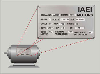
Figure 5.
Part C of Article 430 specifies overload protection requirements for motors, motor controllers, and motor branch-circuit conductors. Section 430-32 (a) requires that each continuous duty (three hours or more) motor rated at more than 1 horsepower must be protected by an overload protective device rated at no more than the following percentages of the motor nameplate rating. Using the values marked on the motor nameplate in Figure 6 the service factor of the motor is 1.15. This is the sizing that is accomplished by the use of the nameplate current value instead of the ampacity value in the table.
• Service factor not less than 1.15 125%
• Motor marked with
Temperature rise not over 40% 125%
• All other motors 115%
Modifications of these values above are allowed if the percentages are insufficient to start the motor or carry the motor load (see Section 430-34). These values in Section 430-32(a) are generally sufficient for general motor applications. Using the full-load current value marked on the motor, as per the requirements of Section 430-32(a)(1), the overload device would be sized at 125% of the value 18.6 amperes. The value, 18.6 amperes multiplied by 125%, results in a value of 23.25 amperes. An overload protective device should be selected not to exceed that value. The manufacturer of a motor starter or motor controller provides a thermal heater selection table with the controller to assist in selecting the properly sized overload device.
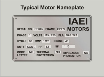
Figure 6.
Section 430-40 in the Code adds some additional requirements to be aware of. Overload protective devices for motor overload protection are generally not capable of opening short-circuits or ground-faults and thus these overload protective devices must be protected by fuses or circuit breakers with ratings or settings in accordance with Section 430-52 or by a motor short-circuit protector in accordance with Section 430-52. Many motor starters and controllers that utilize thermal overload devices also will specify a maximum rating of a fuse or circuit breaker to properly protect the overload device within its short-circuit capabilities. Pulling out the magnifying glass and reading the tiny print on the inside of the magnetic motor starter enclosure is critical to maintaining proper protection and complying with Section 110-10.
Disconnecting Means and Controller
The Disconnect. The rating of the disconnecting means for general motor installations is required to be in accordance with Part J of Article 430. Basically the disconnecting means must be capable of disconnecting the motor and controller from the circuit. The rating of the disconnecting means must have an ampacity of at least 115% of the full-load current rating of the motor, based on the appropriate table in Article 430. The disconnecting means must also have a horsepower rating at least equal to that of the motor or be of any of the other types listed in Section 430-109.
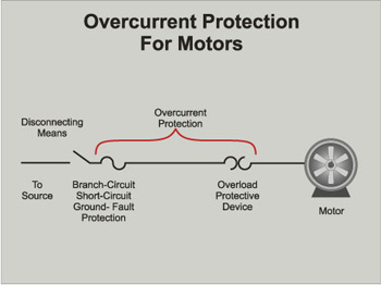
Figure 7. Overcurrent protection for motors
The Controller.A controller is defined as the device that is normally used to start and stop a motor by actually breaking the motor-circuit current. A control device connected to a motor control circuit is not a motor controller. A motor starter and a properly rated (HP) contactor are two forms of motor controllers. Other devices also are permitted to serve as motor controllers. Ratings of the controller or motor starter must be in accordance with Part G of Article 430. Section 430-82 requires each controller to be capable of starting and stopping the motor it controls and to have the capability of interrupting the locked-rotor current of the motor. Section 430-83 details the required controller ratings.
Summary
The total overcurrent protection for a motor, motor branch circuit, and motor control apparatus is provided by the combination of the motor branch-circuit short-circuit and ground-fault protective device (fuses, circuit breakers, or motor circuit protectors) in accordance with Part D of Article 430, used in combination with an overload protective device meeting the requirements of Part C of Article 430 (see Figure 7). Section 430-55 allows a single branch-circuit short-circuit and ground-fault protective device to provide the combined protection when the rating of the branch-circuit short-circuit and ground-fault protective device is set or rated so as to also provide overload protection in accordance with the ratings or settings required in Section 430-32 or 430-34. The Code also provides some references to Example No. D8 in Appendix D which may also assist the inspector and installer in more clearly understanding these requirements for overcurrent protection of motors and motor circuits.


Find Us on Socials