The March/April issue of the IAEI News had an article on high voltage Equipment that discussed the new areas of application. The article discussed how these systems have evolved into some non-traditional areas along with some of the safety concerns for those working around this equipment. Codes and standards were discussed in general along with some issues that come about when over 600-volt equipment is installed. This article will focus on some of the National Electrical Code requirements and common problems being experienced in the field today. Due to space limitations, not every aspect of high voltage installations can be covered in an article like this. All that can be done is to give some insights into common problem areas and hopefully stimulate the reader’s interest to go farther and learn about the proper way to install these systems. Many of the problems seen and discussed in this article are due to lack of training and limited experience on the parts of the design engineers, electrical installers and inspectors. Unfortunately, there are inspectors being asked to do plan reviews and field inspections who have never actually worked on “high voltage” equipment and systems. The combination of an installer with limited qualifications and an inspector with limited experience in this area can make for dangerous situations.

Photo 1. A case where the power cable entry point and termination is below the vent for the fuse

Photo 2. A worker in the blast zone needs personal protective equipment and adequate space to operate the insulated tools, such as shotgun and other hot sticks
Part B of NEC Article 100 adds some definitions that are specific to over 600-volt equipment and systems. These definitions generally cover two broad categories, fuses and switching devices. It is important that these terms are understood so the requirements using these terms later on in the NEC are understood. There are several definitions for fuses including electronically actuated fuses, expulsion fuse, nonvented power fuse, power fuse unit, vented power fuse and multiple fuse to identify the several types that may be encountered. While most of the above fuses operate similarly to low voltage fuses by melting, there are fuses that are actuated electronically which have different rules applied for overcurrent settings and allowances. While fuses for under 600-volt equipment are prohibited from expelling hot gases or other materials, this is not necessarily true for fuses rated over 600 volts. High voltage fuses may or may not expel or vent hot gases that are generated by the arcing as the fuse opens. The energy levels are very high and that pressure generated from the internal melting and arcing needs to be released for some designs. One thing to watch for with fuses that do vent is that there is proper clearance of other components and especially any combustible materials in the direction of the venting. The example photo 1 shows is a case where the power cable entry point and termination is below the vent for the fuse. The fuse in this photograph is vented through a muffler in the lower part to mitigate the noise and arrest any burning materials that are expelled. Other items such as space heaters or control wiring are found installed directly below a vented type power fuse. Another feature of medium voltage fuses is that they may be ganged with two or even three fuses in parallel. While this is generally not acceptable for low voltage fuses, it is fairly common in medium voltage metal enclosed switchgear applications. An item to watch with this is the ratings. It is possible to have a single barrel fuse rated 600 amps, to have a two barrel fuse rated 600 amps or have a three barrel fuse rated 600 amps. The fuse rating is of the single barrel or the combination for the multiple barrels, not the rating of each barrel as has been mistakenly applied in the past with catastrophic results. 
Photo 3. This switchyard has overhead bus supported on several types of structures and insulators
The other main group of definitions deals with switching devices. These include circuit breakers (CBs), cutouts, disconnecting switches, interrupter switches, oil cutouts, and oil switches. Circuit breakers also come as air CBs, vacuum CBs, oil-filled CBs and SF6 CBs. Circuit breakers rated over 600 volts are very different from what is seen with breakers rated 600 volts or less. One main difference is the “”circuit breaker”” is really an electrically operated switch. There are no overcurrent devices built in. The overcurrent protection and control comes from using current transformers (CTs) that may or may not be mounted on the breaker body and protective relays that are mounted in the switchgear assembly. Power is derived from a control source, batteries or control power transformer external to the breaker assembly. Typical breaker ratings are 1200, 2000 and 3000 amps, while the actual application rating depends on the CT ratio and the relay settings. Similarly cutouts, disconnect switches and interrupter switches may or may not be rated for opening load current or fault currents. Familiarity with the equipment and the applicable ratings is essential to understanding the installation requirements and restrictions. 
Photo 4. The purpose of this switch, like the one shown in photo 4, is to provide visible open contacts for all ungrounded conductors to ensure power is disconnected when needed.
Article 110, Part C provides the general requirements for over 600-volt applications. Section 110-30 provides that the requirements of Article 110 Part A, “General Requirements,” apply along with the sections that follow which supplement or modify those requirements. As discussed in the last issue, medium voltage equipment may be enclosed in steel enclosures or it may be open where the room or a fenced area constitute the “enclosure.” In either case, access to over 600-volt equipment is specifically limited to qualified personnel and there must be applicable warning signs. Sections 110-32, 110-33 and 110-34 address the work-space and access requirements to over 600-volt equipment. One key characteristic of over 600-volt equipment is that it is generally physically larger than the under 600-volt counterparts. Also with the higher energy levels present that could severely injure or kill someone, more space is needed. As shown in photo 2, a worker in the blast zone needs personal protective equipment and adequate space to operate the insulated tools, such as shotgun and other hot sticks. Conditions 1, 2, and 3 for working space in Section 110-34 are the same as for under 600-volt equipment in Section 110-26. The voltage references are for the voltage to ground. Remember the definition for “voltage to ground” in Article 100 states that for ungrounded systems, the phase-to-phase voltage is taken as the “voltage to ground” for purposes of determining the working clearance. Also, note that this working clearance for over 600-volt equipment does not depend on the likelihood of accessing while energized as provided in Section 110-26.

Photo 5. These shields shown have limited ratings for current withstand and are there to provide a ground reference around the cable insulation to even out the voltage stress and to provide a return for cable faults only.
The last two items for discussion from Article 110 are the installation of circuit conductors and terminal temperature ratings. Section 110-36 permits several wiring methods and references several sections in Article 300 and Article 490. Where open conductor or bus installations are completed in the field, Section 110-36 also requires the supports and insulators holding these conductors in place have an adequate mechanical rating to withstand the maximum magnetic forces that would be present in the event of a short circuit. As seen in photo 3, this switchyard has overhead bus supported on several types of structures and insulators. These structures and insulators have mechanical load and stress ratings that have to be considered in the design and installation. Section 110-40 on terminal temperatures finds that over 600-volt equipment actually simplifies things. Medium voltage equipment, terminal lugs and cables are all rated at 90°C so ampacities can be taken right from the applicable tables. A review of the cable ampacity tables finds ampacities listed at 90°C and 105°C. The 105°C ampacity could be used for derating calculations where necessary, but the installation cannot exceed the 90°C ampacity maximum allowed for the terminations or equipment.

Photo 6. The concentric neutral has larger conductors, shown in photo 6 as compared to normal stress control wire shielding, and therefore has greater withstand to meet the ground-fault current-carrying requirements.
Article 225, Part C deals with outdoor feeders that operate at over 600 volts. This part requires warning signs where unqualified persons can approach the feeder or equipment as well as isolating switches. Where the building disconnecting means on a feeder is an oil switch or an air, oil, vacuum or sulfur-hexafluoride circuit breaker, an additional disconnecting switch must be installed. The purpose of this switch, like the one shown in photo 4, is to provide visible open contacts for all ungrounded conductors to ensure power is disconnected when needed. The exception permits this disconnect to be eliminated only when the oil switch or the circuit breakers installed in switchgear allows the unit to be racked out of its cell and show positively there is an open circuit. Section 225-53 requires the building disconnecting means to open all ungrounded conductors simultaneously as well as being rated to close into a fault of the maximum available short circuit current available. What this does is effectively rule out using single cutouts for poly-phase systems. 
Photo 7. An installation of some metering was retrofitted into an existing metal enclosed 15 kV class switch
Article 230, Part H addresses services of over 600 volts. As discussed in the previous article, this is becoming very common in many areas. Section 230-200 provides that all the previous requirements for services need to be followed with the section in Part H modifying or supplementing those requirements. A fine print note sends the user to the National Electrical Safety Code (NESC) ANSI/IEEE C2 to determine the required clearances for conductors over 600 volts when installed over sidewalks, roadways, etc. This would be a case where the jurisdiction may have to adopt the NESC to make those provisions enforceable. As with outside feeders in Article 225, warning signs are required where unauthorized persons could come into contact with live parts. This does not apply to metal enclosed and locked equipment. Section 230-204 mimics Section 225-53 requiring the isolating switch so visible contacts are available to verify an open circuit. The same exception for draw out type breakers is also provided. An additional requirement for services is in Section 230-204(d) where a means for grounding the load side conductors after being disconnected must be provided.

Photo 8. For a shielded cable, this minimum radius is 12 times. If the cable is bent too tight, the insulation system is damaged and premature cable failure will occur
As with outside feeders, the service disconnecting means must open all ungrounded conductors simultaneously. This has been a common problem where the “service disconnect” was three individual fuse cutouts on a pole. Where a facility owner owns and controls the over 600-volt distribution system and transformers to provide the utilization voltage, he must have a method to disconnect this equipment as well as provide the proper overcurrent protection. This generally means some sort of ganged switch, pole mounted or in switchgear, or a circuit breaker needs to be installed in the primary of the system. One issue raised by many jurisdictions is having the “service equipment” marked as suitable for service equipment. Unfortunately, the present standards do not cover this aspect for over 600-volt equipment. Some accredited testing laboratories have provided field evaluation services to meet this need by applying the philosophy of UL 869A and adapting it along with the applicable ANSI/IEEE C-37 standard for the over 600- volt equipment. Service overcurrent protection is required by Section 230-208. It should be noted that only short circuit protection is required. The maximum rating for a fuse is three times the conductor ampacity and a protective relay may be set up to six times the conductor ampacity. This is allowed due to the construction of medium voltage cables that have a long term overload capacity. While only short-circuit protection is required by Code, most designs also provide for some level of overload and ground-fault protection. This is explained more in Section 240-100(c). 
Photo 9. For a shielded cable, this minimum radius is 12 times. If the cable is bent too tight, the insulation system is damaged and premature cable failure will occur
Going on to Article 240, over 600-volt systems are covered in Part I. Part I has two sections that address feeders and branch circuits. Overcurrent (short-circuit, ground-fault and overload) protection is required in each ungrounded conductor for both feeders and branch circuits. Section 240-100 requires the overcurrent protection to be selective to prevent damage or dangerous temperatures in conductors or the conductor insulation under a short-circuit condition. Actual settings for limits are not specified. It should be noted that at least one large equipment manufacturer has a fused switch / vacuum interrupter combination that will provide short-circuit and ground-fault protection. Section 240-101 addresses limits applicable to feeders only, similar to services. These limits are three times the conductor ampacity for fuses and six times the conductor ampacity for setting of protective relays on circuit breakers.

Photo 10. The result of an installation of three 1000 kCmil 15 kV conductors run in parallel that has all the – phase conductors in one conduit, all the – phase in the second and all the – phase in the third
Grounding is covered in Article 250 Part K. One interesting note is that this part deals with the grounding of systems over 1000 volts where all the previous discussions have dealt with systems over 600 volts. Most of this part addresses the grounding requirements for system neutrals. Section 250-182 provides that system grounding can be accomplished through a grounding transformer such as a zigzag or Scott-T type unit. The neutral derived from this transformer and connected to earth is the grounding connection for the high voltage system. Section 250-184 provides that solidly grounded high voltage systems may be grounded at one location for each system, as typically seen with low voltage systems, or may be grounded in multiple locations under specified conditions which is more like the typical utility distribution system. This multiple grounding concept is specifically prohibited or severely limited on low voltage systems. Whenever the neutral of the system is solidly grounded, Section 250-184(a) permits the neutral conductor to have 600-volt rated insulation or it may be bare when used as service entrance, underground portions of a feeder or an overhead portion of a feeder. It should be noted that where the outdoor bare neutral conductors come within 10 feet of buildings, the neutral must be covered.
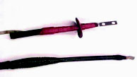
Photo 11. The bottom 15 kV XLPE conductor has an irreversible crimp lug on the conductor and hand made stress cone made from successive layers of tape including semiconductive tape, a filler tape and finally an overall covering for mechanical protection
Another option for system grounding is in Section 250-186 where impedance grounding is permitted. This is slightly different than with low voltage systems as detailed in Section 250-36. The impedance may be a resistor or a reactor and may be a “low impedance grounded system” or a “high impedance grounded system.” There are advantages and disadvantages to each of these methods and many times the system voltage and loads being served will dictate which to use. Low impedance systems allow for greater fault currents and many times have some sort of ground fault-tripping scheme. The high impedance systems limit the ground fault current to a low value tolerable on a continuous basis and have an alarm system instead of tripping. One key item to remember is that the neutral conductor must now be properly identified per Article 200 and must be fully insulated for the system voltage. The reason for this is that under ground-fault conditions, the potential between the neutral conductor and any of the ungrounded conductors will approach the system phase-to-phase potential. Where the impedance grounded system is applied, no other connection of the neutral to ground is permitted. The only connection is through the impedance at the source of supply or at the first disconnecting means. Portable equipment operating at over 1000 volts is covered by Section 250-188, which has several provisions. The supply system serving this type of equipment is required to be impedance grounded or have a grounding transformer for delta systems to derive a ground reference. Equipment grounding conductors are required to bond all non-current carrying parts of portable or mobile equipment. The sizing of the equipment grounding conductors is based on not developing more than 100 volts potential rise between ground and the faulted equipment under maximum ground- fault conditions. Ground detection and relaying is required to de-energize the equipment in the event of a ground fault and additionally, the equipment grounding conductor path has to be continuously monitored for continuity. Many times there is a redundant equipment ground installed with a sensing circuit established between the two equipment grounds such that when interrupted, the supply is immediately de-energized. Lastly, the grounding electrode used for the impedance grounding must be a minimum 20 feet away from any other system grounding electrode and shall not have any direct connection to a fence, underground metal pipe or similar underground metal structures.

Photo 12. The lug used has smooth surfaces and rounded edges which is different than the 600-volt rated lug with cut edges and square corners.
Equipment around high voltage systems such as non-current carrying metal enclosures, associated fences, housings and supporting structures are required to be grounded. This is seen in typical substation arrangements where all aboveground exposed metal structures are grounded directly to the grid constructed under the substation. It should be noted that the metal shield of most medium voltage cables is not suitable to be used as an equipment grounding conductor. These shields shown in photo 5 have limited ratings for current withstand and are there to provide a ground reference around the cable insulation to even out the voltage stress and to provide a return for cable faults only. One exception could be the use of a concentric neutral of a cable assembly for the equipment ground return. The concentric neutral has larger conductors, shown in photo 6 as compared to normal stress control wire shielding, and therefore has greater withstand to meet the ground-fault current-carrying requirements. Article 300 addresses wiring methods. The first section that addresses over 600 volt systems is Section 300-3(c)(2) which prohibits conductors of circuits rated over 600 volts from occupying the same equipment wiring enclosure, cable, or raceway with conductors of circuits rated 600 volts nominal or less unless specifically permitted. So, a simple question arises. For a solidly grounded medium voltage system where the neutral is permitted to be insulated at 600 volts as discussed above, is the neutral permitted to be installed in the same enclosure, raceway or cable tray with the ungrounded conductors? Many jurisdictions have interpreted this section to say that this is prohibited. What has to be read carefully is that this is not a prohibition based on insulation rating but on the rating of the circuit. The 600-volt insulated neutral is part of that over 600 volt circuit and is not part of a circuit rated 600 volts nominal or less. It would seem that the answer to the question would be that it is allowed. Some of the provisions where over and under 600 volt circuits may occupy the same enclosure, raceway or cable include electric discharge lighting as provided in Section 300-3(c)(2)(a) and (b). Certain motor or generator high and low voltage conductors are permitted to be together. It is also permitted in switchgear, MCC’s and control gear and in manholes if there is separation and securing. Photo 7 shows where an installation of some metering was retrofitted into an existing metal enclosed 15 kV class switch. In this case the low voltage wiring is permitted because this meter is part of the system. The violation here is from Section 490-35(b) requiring the meter equipment itself to have barriers and also that there is inadequate clearance between the uninsulated live high voltage parts and the low voltage wiring, as well as infringement on the air space for heat dissipation on this one phase. Article 300 Part B addresses over 600 volt wiring methods. Section 300-32 is about conductors of different systems and sends the reader right back to Section 300-3(c)(2), which was just discussed. Section 300-34 addresses cable bending radius. To understand the reasons behind the bending radius requirements, one needs to understand the differences in cable construction between low and high voltage conductors. Low voltage conductors generally have a single layer of insulation extruded onto the conductor. The voltage stress on the insulation is minimal for the thickness used and the insulation provides adequate mechanical protection. Medium voltage cables are constructed as a system to provide the insulation level needed, seal for gaps to prevent damage from corona discharge, and to provide shielding for an even ground reference. Cables rated 2000 volts or less may have a metal shield layer or not. Cables rated above 8000 volts must have a metal shield. These requirements are from Section 310-6 and the exception.
Photo 13. An example of a problem created in the field
The typical medium voltage cable construction starts with the conductor just like low voltage conductors, but this is where the similarity ends. On the medium voltage cables, a thin semi-conductive layer is extruded onto the conductor to fill the voids between the strands and make a voltage stress transition to the insulation layer. Most cables today use a solid dielectric insulating material such as cross linked polyethylene (XLPE) or ethlene-propolyene rubber (EPR). The thickness of this insulation layer is dependent on the voltage level and also from being rated for use on a grounded system or an ungrounded system. For example, the 15 kV cable in photo 6 would have a thickness of 175 mils for a 100 percent rating and 220 mils for a 133 percent rating. Over this insulation is another semiconductive layer that is extruded over the insulation. This layer is to provide a voltage stress transition between the outer surface of the insulation to the metal shielding. This metallic shield can be a tape or stress control wire type as shown in photo 5. The tape is overlapped to provide a complete envelope, while the wire type is spiral wound around the cable. The final layer is a jacket that is extruded on to provide mechanical protection when pulling into a conduit or from other physical damage. The minimum bending radius for an unshielded (no metallic shield) cable is 8 times the overall diameter of the cable assembly. For a shielded cable, this minimum radius is 12 times. If the cable is bent too tight as shown in photos 8 and 9, the insulation system is damaged and premature cable failure will occur. In photo 8, the diameter of the cable is approximately 1 inch. With the full circle bend, the space needed would be 2 times the minimum bending radius or 24 times the cable diameter. This equates to 24 inches. Since the conduit enters in the center, this cabinet would have to be at least 48 inches wide. In fact, this cabinet is just under 36 inches wide, so either the conduit should have entered toward a side or the cable should not have been routed with a full circle. Photo 9 is a 21 kV transformer installation recently completed at a residence. The cable diameter is approximately 1-1/2 inches. The left cable bend going to the load break elbow is 1.1 times this diameter where the minimum is 12 times. The installer commented he knew nothing in the Code, manufacturer’s instructions or UL that specifies bending radius so there could not be a problem. The manufacturer was sent the picture for comment and the reply came back with the installation instructions that are published with a bending radius of 12 times. The manufacturer predicts that this cable will fail at that bending point within a very few years.
Section 300-35 specifies that installations shall be made to prevent inductive heating. This means that all cables of a circuit need to be routed together where going through metallic conduit or penetrating enclosures. For a circuit with parallel conductors, each conduit needs to have one conductor of each phase, a neutral if applicable, and equipment grounding conductor as applicable. Photo 10 is the result of an installation of three 1000 kCmil 15 kV conductors run in parallel that has all the ‘A’ phase conductors in one conduit, all the ‘B’ phase in the second and all the ‘C’ phase in the third. No neutral was installed and an equipment grounding conductor was installed in each conduit. The raceway was non-metallic rigid conduit except for one sweep ell in each run that was rigid steel conduit. The cable fault occurred a couple of days after being energized at light load due to inductive heating. The fault path was from one phase to the conduit ell through the concrete encasement to the next phase in another conduit.
Section 300-37 provides the acceptable above-ground wiring methods for over 600 volt installations. Wiring methods that have been in the NEC for many years include rigid metal conduit, intermediate metal conduit, rigid nonmetallic conduit, cable tray, busways and cablebus. New to the 1999 NEC was the addition of electrical metallic tubing. Additional wiring methods that can be used include other identified raceways, open runs of metal-clad cable suitable for the use and purpose, and where access is limited to only qualified persons, open runs of MV cable, bare conductors and bare busbars. It should be noted that the “other raceways” not specifically listed above have to be “identified.” Article 100 defines this as “recognizable as suitable for the specific purpose, function, use, environment, application, etc., where described in a particular Code requirement.” The fine print note following this definition offers the guidance that the determination of suitability may be achieved by evaluation, listing and labeling by a recognized testing laboratory, inspection agency or other organization concerned with product evaluations.
Cable terminations are covered in Section 300-40. The requirements seem pretty simple where one has to cut back the metallic and semiconductive shielding layers for a sufficient distance depending on the system voltage. After stripping back these shields, a stress reduction means needs to be applied at the termination of the shielding along with the termination of the actual conductor. Lastly, the metallic shield and associated semiconductive components must be grounded. Many years ago, splicing or terminating high voltage cables was a specialty with some art and a lot of skill involved. In photo 11, the bottom 15 kV XLPE conductor has an irreversible crimp lug on the conductor and hand made stress cone made from successive layers of tape including semiconductive tape, a filler tape and finally an overall covering for mechanical protection. Note the long distance from the end of the conductor to the beginning of the stress cone. This is that cut back distance addressed by Section 300-40. Today, most splices and terminations are done with kits and completed by individuals with a wide variance of skill or training in the proper installation of the kit. Most of the termination manufacturers will provide training and some supervision for free or at a nominal cost, but not all installers will take advantage of this service. The top termination in the photo is an example of a stress cone kit on a 15 kV EPR cable. The extra boot or skirt in the top photo is to increase the surface distance between the conductor and the metallic shield where subject to contamination and weather. The metallic braid seen at the top left is the grounding connection to where the metallic shield ended. The majority of cable failures today, either found through high potential testing or as failures in service, are the result of poor installation of the splices or stress cone terminations.
The last part of Section 300-40 addresses the grounding of the metallic shield. The requirement is for this shield to be grounded wherever it is exposed, meaning at all splices and terminations. This provides the highest level of safety, whereas grounding at only one point could have an expo