Requirements for overcurrent protection for conductors are found in Article 240, Overcurrent Protection, which is found in chapter two, Wiring and Protection, of the NEC. Electrical conductors are required to be protected against overcurrent in accordance with their ampacity ratings that are specified in Section 310-15. Chapter three covers wiring methods, and the conductors installed in conjunction with those wiring methods must follow the applicable requirements of Article 310, Conductors for General Wiring.
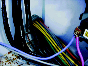
Photo 1. Correction factors for number of current carrying conductors may be required per 310-15(b)(2)(a)
Conductor Ampacities
Generally, conductors are required to be protected in accordance with their ampacities given in the appropriate tables in Article 310, after any adjustment or correction factors have been applied for number of current-carrying conductors in the same raceway, cable, or trench, etc., and if installed in ambient temperatures other than those for which the conductor ampacity value in the table is applicable (see photo 1).
An electrical conductor has two ampacity ratings: a long-time rating and a short-time rating. The long-time ratings for electrical conductors for general wiring are specified in the tables in Article 310. A conductor short-time rating is another way of referring to a conductor’s withstand rating. The short time ratings for conductors are not given in the NEC, but should be given consideration as part of electrical design. Section 110-10 requires OCP devices to be selected and coordinated to clear faults without extensive damage. See also 310-10.
An insulated conductor has a five-second withstand rating of approximately 1 ampere for every 42.25 circular mil area of conductor. For more detailed information on the short circuit withstand capabilities of conductors refer to chapter 11 of IAEI’s Soares Book on Grounding. This article will focus on protection of conductors in accordance with their long-time ampacity ratings. These are the ampacities specified in the tables in Article 310.1
These ampacities are the values of current that the conductor can carry without causing damage or degradation of the conductor. Conductors that are not provided with properly sized overcurrent protective devices are subject to over heating and insulation failures which ultimately lead to ground fault and short circuits in the wiring system.
The Code on Overcurrent Protection of Conductors
Section 240-3 requires conductors to be protected against overcurrent in accordance with their ampacities in Section 310-15. Immediately there is a sense of Section 310-15 working hand in hand with the requirements of Section 240-3 and rightly so. Section 310-15(a) allows the ampacities for conductors to be determined from the tables or under engineering supervision. This article will focus on the use of the tables only. Section 310-15(b) requires that the ampacities for conductors rated 0-2000 volts be as specified in the Allowable Ampacity Tables 310-16 through 310-19 and the Ampacity Tables 310-20 and 310-21 as modified by Sections 310-15(b)(1) through (7).
A look at Table 310-16 and the title of the table reveals that the ampacity values given in the table are based on two conditions. First, the ambient temperature the conductors are installed in is based on 86°F (30°C) and not more than three current-carrying conductors are installed in the same raceway, cable, or earth. If either of these conditions in the title of Table 310-16 varies, some adjustment based on the conditions of use will have to be made. It is important to properly protect the conductor at the adjusted ampacity if correction factors have to be applied.
Section 310-15(b)(2) requires an ampacity correction factor when the number of current-carrying conductors in a raceway or cable exceeds three or where single conductors or multiconductor cables are stacked or bundled together without maintaining spacing in distances longer than 610 mm (24 in.). The adjustment factor percentages are given in Table 310-15(b)(2)(a).
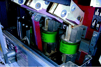
Photo 2. Fuses as overcurrent protective devices for equipment and conductors
Neutrals are current-carrying conductors. The amount of current a neutral carries is based on the unbalanced return current of the ungrounded conductors of the common multiwire branch circuit. Neutrals must be counted as current-carrying conductors if either conditions of 310-15(b)(4)(b) or (c) are applicable to the circuit. Many neutral conductors of individual circuits as well as multiwire branch circuits these days are often counted as current-carrying because of the large amounts of nonlinear loads (see sidebar) containing harmonic currents imposed on the return neutral of the circuit. Electronic equipment, electronic/electric-discharge lighting, adjustable-speed drive systems, and similar equipment are examples of the types of equipment that could be nonlinear loads.
So several factors come into play when determining a final conductor ampacity for any given electrical circuit, and each must be considered and factored into the protection of the conductor (see photo 2).
Next Higher Rated Overcurrent Device
When the ampacity of a conductor does not correspond to a standard ampere rating of a fuse or circuit breaker without overload trip adjustments above its rating, the overcurrent device is permitted to be the next higher standard rated device given in Section 240-6 provided the conductors being protected are not part of a multioutlet branch circuit that supplies receptacles for cord-and plug-connected portable loads and the next higher standard rated device does not exceed 800 amperes.
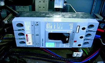
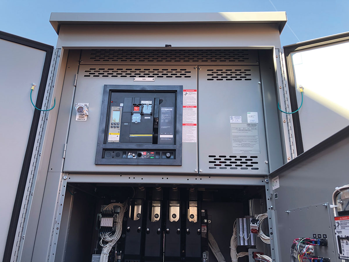
Photo 3. Circuit breakers as overcurrent protective devices for conductors and equipment
Where the overcurrent protective device for the conductor exceeds 800 amperes, the ampacity of the conductors is required to be equal to or greater than the rating of the overcurrent device as defined in Section 240-6. The main reason for the limitation on devices rated at over 800 amperes is simply that the standard rated devices over 800 amperes start increasing in increments greater than 100 ampere increments. In fact, at 3000 amperes the increments for standard rated devices start increasing by 1000 amperes each up to 6000 amperes.
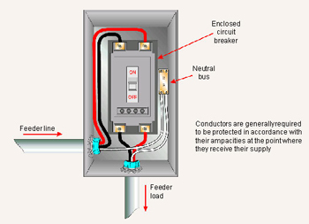
Figure 1. Conductor overcurrent protection
Two things are very important when working Section 240-3 with Section 240-6. Make sure that (1) the conductor has enough ampacity for the load to be served, and (2) the next standard size device still properly protects the conductor after adjustment factors have been applied to it (see photo 3).
Location of the Overcurrent Device in the Circuit
A fuse or circuit breaker is required to be connected in series with each ungrounded conductor. The overcurrent protection must be provided in each ungrounded circuit conductor at the point where the conductors receive their supply (see figure 1).
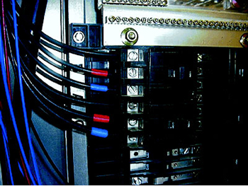
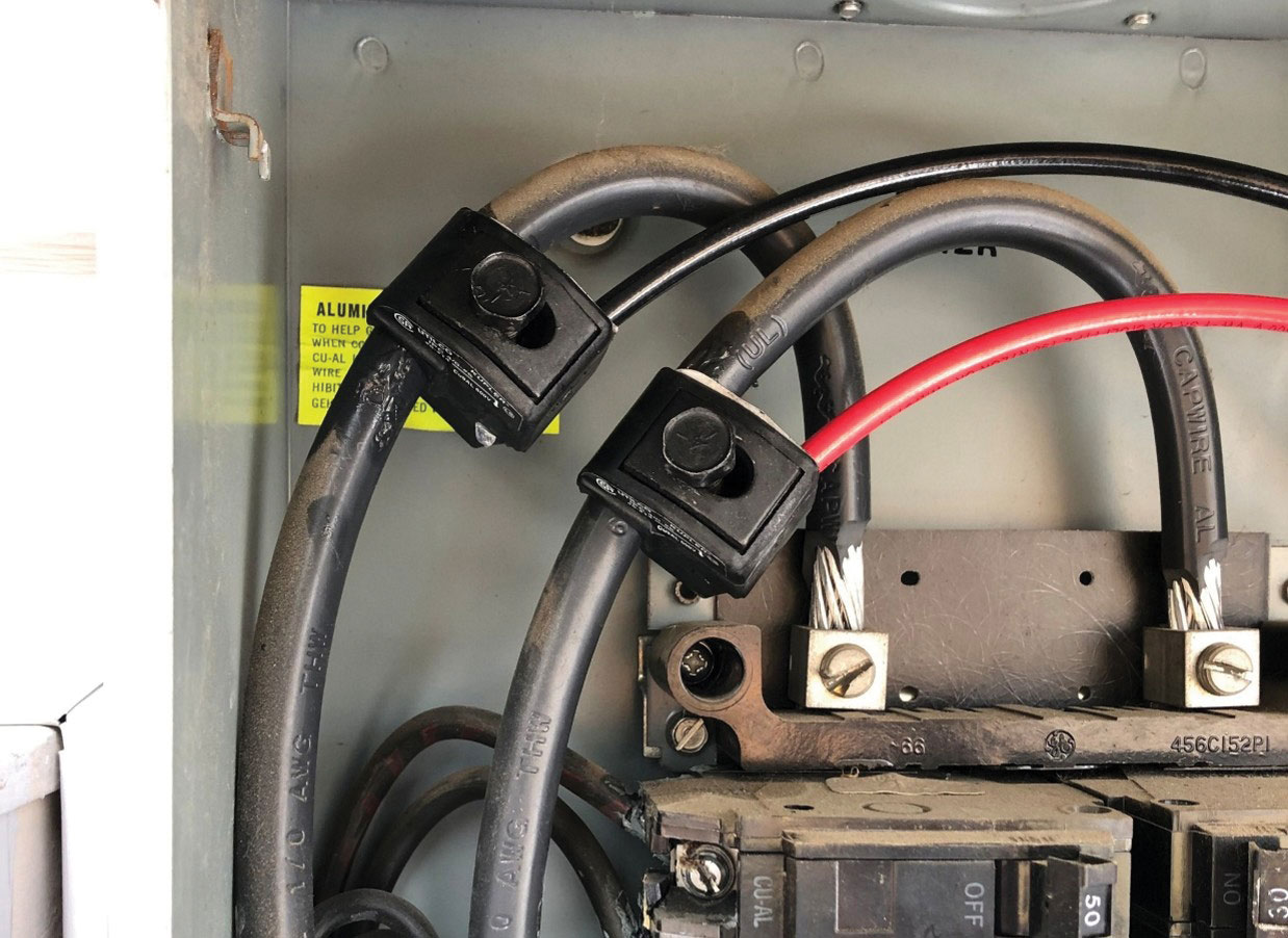
Photo 4. Conductors protected at the point they receive their supply
This requirement in the Code works well for conductors that originate from a panelboard or a switchboard where the overcurrent protection is an integral part of the device that is directly connected to the bus of the equipment and then properly fused (see photo 4).
Tap Conductors
There are cases where it is physically impossible to meet these requirements without a length of conductor that is not protected at the point where it receives its supply. These situations or conditions are what the NEC refers to as “tap conductors.” Tap conductors are permitted in various locations in electrical circuits. Branch-circuit tap conductors are permitted within the limitations of Section 210-19.
The 1999 NEC made two clarifications relative to tap conductors that work to clarify any gray areas or confusion that may have been previously associated with tap conductors. The first revision to the Code addressing tap conductors shows up in Section 240-3(e). Here the term “tap conductor” is defined as “a conductor, other than a service conductor that has overcurrent protection ahead of its point of supply, that exceeds the value permitted for similar conductors that are protected as described elsewhere in” Section 240-3. Section 240-3(e) permits tap conductors to be protected against overcurrent in accordance with Sections 210-19(d), 240-21, 364-11, 364-12, and 430-53(d). The second and very important clarification that was made in the 1999 NEC was that it is not permitted to tap a conductor that is already functioning as a tap conductor. This is commonly referred to as “tapping a tap.” The Code never has permitted tapping a tap conductor; it was just one of those gray areas that needed clarification. The clarification was made in Section 240-21. Here, the last sentence of this section states: “No conductor supplied under the provisions of (a) through (g) shall supply another conductor under those provisions, except through an overcurrent protective device meeting the requirements of Section 240-3.”3
This revision did two things: it clarified that tapping a tap is not permitted, and it also clarified that service conductors do not fall under the requirements for tap conductors, just feeders and branch-circuit conductors. Service-entrance conductors fall under the requirements of Part G of Article 230.
It should be understood that when a tap conductor is permitted by the Code, it allows the conductor to be connected to the source, either a feeder or a transformer or other source, and installed without any overcurrent protection for any of the lengths specified in Section 240-21 based on which tap rule is being applied.
The Code recognizes the need for this length of unprotected conductor and has specific rules in place that provide equal and effective means of protecting the sacrificed conductor. Most of the tap rules in Section 240-21 require that the tap conductors terminate in a single overcurrent device or set of fuses that will limit the load to the ampacity of the tap conductors.
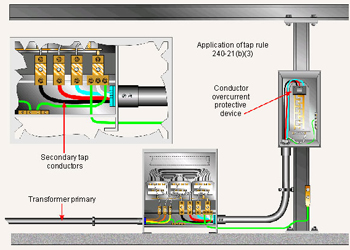
Figure 2. Tap conductors to transformer secondary
Other requirements for tap conductors may include a length limitation, protection from physical damage, and sizing requirements. Each specific tap rule found in Section 240-21 must be applied specifically to the conditions of use. Remember that the Code is allowing the sacrifice and installation of unprotected conductors for a given length. All of the requirements in each of the tap rules must be followed based on the particular tap conductor requirements. Tap rules will be covered in detail in upcoming issues of the IAEI News (see figure 2).
Overcurrent Protection of Equipment
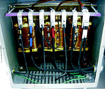
Photo 5. Tap conductors connected to transformer secondary
Overcurrent and overload protection requirements for equipment can vary based on the type of equipment being protected. For example, transformers are required to be protected against overcurrent in accordance with Section 450-3. The tables in 450-3 provide guidance as to the types of protection methods employed for the transformer itself. Two methods are given and the maximum allowable percentages are given. The transformer is permitted to be protected by an overcurrent protective device on the primary only, or by using the combination of a primary and secondary overcurrent protective device to protect the transformer. The overcurrent protection specified in Article 450 is for the transformer only. Section 450-3 FPN refers to Article 240 for protection of conductors. These two methods of protection for transformers 600 volts or less are identified in Table 450-3(b). Overcurrent protection for transformers over 600 volts is covered in Section 450-3(a) and Table 450-3(a).
For motors and air-conditioning equipment, the overcurrent protection requirements are specified in those particular articles. Overcurrent protection for equipment will be covered in another article in coming issues of the News.
Summary
When protecting conductors in accordance with their allowable ampacities, there are many considerations that must be taken into account. Allow for adjustment and application of correction factors as required. Limit the load on the conductor to that for which the conductor is capable of carrying within its ampacity ratings.
When applying any of the tap rules in Section 240-21 for tap conductors, be sure that all conditions of the tap rule have been complied with upon completion of the installation or inspection. Conductors are required to be protected in accordance with their allowable ampacities and equipment is also required to be protected against overcurrent.
Overcurrent protection for switchboards and panelboards is specified in Section 384-16, and for transformers, see Sections 450-3(a) and (b) and Tables 450-3(a) and (b). There are many other types of equipment, such as motors and HVAC equipment, that have specific requirements for overcurrent protection covered by the rules in the NEC. It is important to work these Code sections in harmony with one another to achieve all of the minimum required overcurrent protection anticipated by following the rules in the Code. Various local jurisdictions may amend or supplement the National Electrical Code. Always consult the local authority having jurisdiction if there are doubts or questions regarding the minimum electrical code requirements in that area.
1 Article 310, NFPA 70,National Electrical Code, 1999 Edition, (Quincy, MA: National Fire Protection Association, Inc.), p. 70-116-140.
2 Article 100, NFPA 70,National Electrical Code, 1999 Edition, (Quincy, MA: National Fire Protection Association, Inc.), p. 70-23.
3 240-3, NFPA 70,National Electrical Code, 1999 Edition (Quincy, MA: National Fire Protection Association, Inc.), p. 70-71.


Find Us on Socials