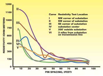
After completing the soil resistance measurements at the proposed substation site, the next step is the development of a mathematical equivalent soil model that is a good approximation of the actual soil resistance data. The most common models are the uniform soil model and the two-layer soil model. The uniform soil model should only be used when there is very little variation in the average resistivity with position and depth. The average resistivity referred to in IEEE Standard 81-1983 is the same as the apparent resistivity referred to in IEEE Standard 80-2000. Further discussion of the uniform soil model can be found in Clause 13.4.1, page 56 of Std. 80. More commonly, the resistivity varies greatly with depth. The following plot of soil resistivity versus rod spacing is a more typical example of soil resistance variation with depth. [See Figure 1]
There are three ways to develop the two-layer model. Clause 13.4.2, page 57 of Std 80, describes a graphical method for approximating a two-layer soil model. Appendix B, page 38 of Std 81, presents a mathematical method for determining the two-layer soil model. The mathematical method described in Appendix B is the basis for several computer programs that can be used to develop a two-layer soil model that best fits the resistance data. One such program is available from the Electric Power Research Institute.
Design Procedure
Clause 16.4, page 88 of Std 80, presents a step-by-step procedure for the design of a substation grounding system. The forty design parameters, which must be calculated to verify the design meets the safety requirements of Clause 4, are listed in Table 12, page 89 of Std 80. Annex B, page 129 of Std 80, presents sample calculations. Computer programs based upon Std 80 and 81 are also available to do most of the calculations.