Newly appointed Executive Director J. Phillip Simmons approached me and asked if I knew where Eustace C. Soares got his information to develop the tables for his book, Grounding Electrical Distribution Systems for Safety. Phil was referring particularly to those related to acceptable lengths of steel conduit and tubing for equipment grounding. I told Phil that I did not know but would try to find out. He told me that IAEI was interested in including this empirical data to back up the information in the 1993 revision of Soares Book on Grounding, 5th edition. Phil asked if the steel conduit manufacturers would consider sponsoring testing to validate the data in the Soares tables. I made some calls to old friends that knew Eustace Soares personally. They did not believe he had done any actual testing to write the book and develop the tables. They thought the data he had used was from old IEEE papers and testing done by R.H. “Dick” Kaufmann in the early 1950s.
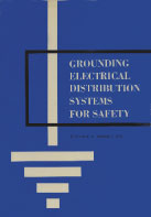
Photo 1. Original Grounding Electrical Distribution Systems for Safety by Eustace C. Soares, copyright in 1966
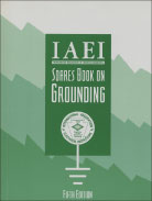
Photo 2. After IAEI acquired the rights to the Soares publication, it was renamed Soares Book on Grounding as shown in this fifth edition revised in 1993
Although the IAEI request was the major factor in deciding to develop GEMI, another factor was revisions to the 1993 NEC. For example, “250-95 Exception 3 Where a raceway or a cable armor or sheath is used as the equipment grounding conductor, as provided in sections 250-51, 250-57(a), 250-73 and 250-91(b).”
The changes made it clear that all metallic raceway, metallic armor or metal-sheathed, copper and aluminum equipment grounding conductors, or the combination thereof, must be sized and installed in a manner that creates a permanent, low-impedance circuit capable of safely carrying the maximum ground-fault current likely to be imposed on it from any point on the wiring system. The conduit and tubing manufacturers wanted to be able to provide documentation that their steel conduit met these NEC requirements and provided an excellent low impedance ground fault return path. Although the NEC section references have changed, the basic requirements have not. All of the equipment grounding conductors in NEC 2002 Section 250.118 are only acceptable if they are sized to provide this required effective ground-fault current path in the event of a ground fault.
NEC 2002 110.10
The overcurrent protective devices, the total impedance, the component short-circuit current ratings, and other characteristics of the circuit to be protected shall be selected and coordinated to permit the circuit-protective devices used to clear a fault to do so without extensive damage to the electrical components of the circuit. This fault shall be assumed to be either between two or more of the circuit conductors or between any circuit conductor and the grounding conductor or enclosing metal raceway.
NEC 2002 250.4(A)
“(3) Bonding of Electrical Equipment. Non–current-carrying conductive materials enclosing electrical conductors or equipment, or forming part of such equipment, shall be connected together and to the electrical supply source in a manner that establishes an effective ground-fault current path.
“(4) Bonding of Electrically Conductive Materials and Other Equipment. Electrically conductive materials that are likely to become energized shall be connected together and to the electrical supply source in a manner that establishes an effective ground-fault current path.
“(5) Effective Ground-Fault Current Path. Electrical equipment and wiring and other electrically conductive material likely to become energized shall be installed in a manner that creates a permanent, low-impedance circuit capable of safely carrying the maximum ground-fault current likely to be imposed on it from any point on the wiring system where a ground fault may occur to the electrical supply source. The earth shall not be used as the sole equipment grounding conductor or effective ground-fault current path.”
Mr. Simmons’ request was presented to the NEMA 5RN Technical Committee and they agreed to sponsor the testing. The first priority was to select a facility and electrical research scientist with impeccable credentials. Section Chairman Al Flanders, Picoma, and Bill Beile, Allied Tube and Conduit, resolved this by locating the top expert in the field of grounding, Dr. A. P. “Sakis” Meliopoulos with the Georgia Institute of Technology (GA-Tech). Dr. Meliopoulos had presented numerous papers on the subject and was highly respected. The School of Engineering at GA-Tech was capable of providing both the facility and the credibility we were looking for. I then told Phil Simmons we would do the testing.
The first step was to develop a scope for the project. This was accomplished by Dr. Meliopoulos’ review of Soares Book on Grounding. He checked the tables using existing data on the properties of steel conduit and tubing such as the resistance and permeability of the steel. Based on that information, Dr. Meliopoulos reported that testing could be done and a computer program could be developed to confirm the calculations. An agreement was reached between GA-Tech and NEMA 5RN Section to proceed.
The next step was lab tests. These were all done at GA-Tech. They obtained conduit and tubing from local supply houses, which they used for developing new data. All the existing data on steel was obtained from old process (Bessemer Furnace) steel. The conduit today is made from steel produced in electronic furnaces, a much cleaner process. Therefore, updated resistance and permeability tests were needed.

Photo 3 & 4. Kearney Laboratories Outdoor Test Site in McCook, Illinois.
Photo 3 and Photo 4. Kearney Laboratories Outdoor Test Site in McCook, Illinois. This is the large transformer used for the tests and all data was recorded with instruments inside the building. All data was recorded by Kearney’s engineering department and Dr. Meliopoulos using separate test instruments. This was done to validate the data.
Computer Model Validation
Based on this new information and computer modeling, a preliminary report was developed and presented to NEMA 5RN. At that time, we were told that the next step was to conduct actual testing to validate the computer model. Dr. Meliopoulos informed us that Kearney Laboratories in McCook, Illinois, had a transformer suitable for this type of testing. Arrangements were made and a licensed electrical contractor was hired to make the installation. We selected conduit and tubing from different manufacturers. We also selected fittings from several manufacturers—set-screw, compression, and both zinc die-cast and steel. The tests consisted of 10 runs of various sizes and types of conduit and tubing with THWN conductors. The 256-foot runs were installed on wood timbers. The length of the runs was limited by the amount of space available at the testing site. About 90 high current and low current tests were performed. Duplicate readings were made by Dr. Meliopoulos and Kearney Laboratories engineers. Arc-voltage tests were also performed to determine the minimum at which an arc can be sustained. The tests confirmed that steel conduit and tubing are excellent low impedance equipment grounding conductors. The die-cast and steel EMT couplings performed equally without arcing or heating.

Photo 5. Conduit supported on timbers running 256 feet from the transformer to the property line in McCook, Illinois
Software Developed
Following the field testing, Dr. Meliopoulos prepared a written report and usable software. The first edition, in 1994, was called Short Circuit Analysis (SCA 1.0). This was DOS-based software. In 1996, GA-Tech converted SCA 1.0 to GEMI 1.0, which was a Windows-based program for “single circuit analysis.”

Figure 1. The GEMI program will calculate the safe low impedance grounding return path for EMT, IMC, RMC, aluminum RMC, copper conductors, aluminum conductors or the conduit or tubing with a supplemental grounding conductor enclosed
Dr. Meliopoulos was able to determine that the original Soares tables developed almost thirty years earlier were essentially correct. He found only minor differences and only a few errors. It is important to note that when a fault occurs in a circuit, all resistance must be calculated including the circuit conductor and the return path to establish the total impedance in the fault path.

Figure 2. The slide shows the single circuit analysis for a 200-ampere circuit enclosed in (RMC) galvanized rigid steel conduit. All inputs are selected by the user
For example, when designing or selecting a wiring method to install a 200-ampere 208/120-volt

Photo 6. Electrician pulling wire at the test site.
feeder to a sub-panel in a large warehouse located 250 foot from the service to comply with 110.10 and 250.4(A) (3), (4) and (5):
- RMC (Article 344) would be in compliance for a run of up to 363 feet.
- IMC (Article 342) would comply for a run up to 389 feet.
- EMT (Article 358) would be in compliance for a run of up to 390 feet.
Other wiring methods not utilizing steel conduit or tubing, but utilizing only a copper or aluminum equipment grounding conductor sized to Table 250.122 would not comply without increasing the sizes.
- Copper conductor sized to 250.122 would be in compliance for a run up to 201 feet.
- Copper conductor oversized to a 4 AWG would be in compliance for a run up to 286 feet.
- Aluminum conductor sized to 250.122 would be in compliance for a run up to 195 feet.
- Aluminum conductor oversized to a 2 AWG would be in compliance for a run up to 277 feet.
Note: as you can see, compliance is obtainable using any of the methods permitted in 250.118. However, GEMI makes the necessary calculations very easy. The program retains the parameters of the last designed system, so you can quickly and easily change raceways and conductors and recalculate.

Figure 3. This table was developed using the data calculated from GEMI.
Power Quality and Harmonics
Soon after the Windows®-based program became available, we began to receive requests from industry to add another feature to the program. We were told there was a need in the industry to evaluate the capability of steel raceways to shield electromagnetic fields in order to reduce electromagnetic interference (EMI) and harmonics affecting power quality issues. With the shift from mechanical relays and gear drives to variable-frequency drives and solid-state devices, design and operations engineers were faced with new power quality and EMI issues. Sensitive computers are being affected by flickering and wavy screens and electronic equipment in offices and industrial processes are being disrupted by data error. Engineers must now deal with EMI, harmonics and power quality issues.

Figure 4. The network analysis allows the user to design or evaluate existing installations.
The next phase of testing to address these issues was sponsored by the steel conduit and tubing manufacturers through the Steel Tube Institute of North America.

Figure 5. Example of a steel conduit magnetic field plot at indicated distance
We again met with Dr. Meliopoulos at GA-Tech and he told us only laboratory tests were needed to add the additional features to the GEMI software. An agreement was reached and a written report was developed, laboratory testing was completed, and the software was revised to include limited provisions to make “network analysis” calculations. This addition (from single circuit) would provide engineers with a tool for calculating the electromagnetic field intensity in milligauss around power circuits for effective conduit design. A multiple frequency feature was added for harmonic calculations.

Figure 6. Example of an aluminum conduit magnetic field plot at indicated distance
GEMI Design Capabilities
Calculate and size equipment grounding conductors
- RMC Rigid Metal Conduit (steel)
- RMC Rigid Metal Conduit (aluminum)
- IMC Intermediate Metal Conduit (steel)
- EMT electrical metallic tubing (steel)
- Copper conductors
- Aluminum conductors
- RMC w/ supplementary ground wire
- IMC w/ supplementary ground wire
- EMT w/ supplementary ground wire
Calculate magnetic field intensity around power circuits at multiple frequencies.
Analyze new or existing wiring installations with linear and nonlinear loads.
GEMI Research Continues

Photo 7. Electricians pulling wire, with Russ Higginbottom, Triangle Conduit & Tubing, overseeing
The conduit producers at the Steel Tube Institute of North America continue to sponsor in-depth research on electromagnetic fields. To address power quality and new design problems, Dr. A. P. “Sakis” Meliopoulos at the Georgia Institute of Technology, Atlanta, is specifically researching how to reduce the EMF effect on electrical and electronic equipment. The results, combined with earlier GA-Tech studies on grounding and early editions of the GEMI software have been developed into a research project through the Power Systems Engineering Research Center (PSERC). The first project was completed December 31, 2003. The newest edition GEMI W2.20 is now available to download for free atwww.steelconduit.org.
The new software provides real time, reliable calculations based on your actual design parameters.
Power Systems Engineering Research Center (PSERC)

Photo 8. Ten runs of RMC, IMC, and EMT metric designator sizes 16 (1/2 trade size) through 78 (3 trade size) connected to the transformer for high current and low current tests.
PSERC consists of universities working with industry to find innovative solutions to challenges facing a restructured electric power industry and to educate the next generation of power industry engineers.
The electric power industry is evolving from its historical business structure. The Power Systems Engineering Research Center (PSERC) draws on university capabilities to creatively address these challenges. Under the banner of PSERC, multiple U.S. universities are working collaboratively with industry to:
- engage in forward-thinking about future scenarios for the industry and the challenges that might arise from them;
- conduct research for innovative solutions to these challenges using multidisciplinary research expertise in a unique multi-campus work environment;
- facilitate interchange of ideas and collaboration among academia, industry and government on critical industry issues;
- educate the next generation of power industry engineers.
Conclusions
Specific conclusions from the EMI research program are:
1. PVC conduit does not reduce electromagnetic fields from power circuits.
2. Aluminum conduit is practically ineffective in reducing electromagnetic fields at power frequency (60 Hz). Magnetic field reduction in aluminum conduit encased power systems is on the order of 10%. At higher frequencies the effectiveness of aluminum to shield against electromagnetic fields increases.
3. Steel conduit is very effective in reducing electromagnetic fields at power frequency (60 Hz). Magnetic field reduction in steel conduit encased power systems is on the order of 70% to 95%.
4. None of the conduit provides shielding against the contribution to electromagnetic fields from ground currents.


Find Us on Socials