What do fuel cells, photovoltaics, and some wind turbines have in common? If they are supplying electricity to a facility and are also capable of supplying excess energy back to the local utility, it is likely they contain a utility-interactive static power inverter. In fact, the static power inverter is one of the major keys to the future success and growth of all alternative energy technologies (see figure 1).

Figure 1. Utility-interactive inverter
Fundamentally, all inverters transform incoming direct-current (dc) electricity, into some well-defined and desirable alternating-current (ac) output. The static power inverter is so named to differentiate it from rotating alternator/generator sets. An inverter uses power transistors that are switched on and off in a controlled manner to synthesize an ac output voltage and current waveform from its dc input. This article provides some background on static inverters with a particular emphasis on the utility-interactive inverter. Utility-interactive inverters are unusual in that they require not only electrical inspector approval, but the local utility’s as well. It is this blending of electrical safety issues and utility performance concerns that makes this equipment unique from both an inspector approval and testing lab evaluation standpoint. This article explains some of Underwriters Laboratories Inc. (UL) requirements for evaluating these products, the utility performance concerns unique to utility-interactive static inverters, and the relevant 2002 National Electrical Code (NEC) requirements.
State of Alternative Energy Technologies
To understand the approximate number of inverters in operation, it is important to quantify the present number of utility-interactive alternative energy facilities in the U.S. This information is also intended to help put some perspective on the number of projects that likely required electrical and utility inspection. The short story is that the number of U.S.-installed utility-interactive alternative energy systems is currently small, less than approximately 5,000 units, but growing at double-digit rates based on data from 1998 through 2002. This means that although this equipment may not be commonplace now, it has the potential to be within a few years.
A recent study by the National Renewable Energy Laboratory (NREL) concluded that there were approximately 2,149 on-grid (or utility-interactive) PV installations in the U.S. through 2000.1 Through 2002, the number of U.S. installations has increased to approximately 2,500 with a 4-year compound annual growth rate of 34 percent; however, in the past two years the rate has declined to around 6 percent.2
There are fewer installed fuel cells, with worldwide numbers roughly equal to the U.S. PV installations. According to a Fuel Cell Today survey, there are some 1,900 stationary fuel cells, ranging in power from 500 W to 10 kW 3 and some 650 units, ranging in size from 10 kW to 11 MW that have been installed worldwide.4 The four-year compound annual growth rate for the 500 W – 10 kW group is 155 percent but only 9 percent for the 10 kW to 11 MW sizes. These studies indicate that potentially 1,800 total units are installed in North America with the majority located in the U.S.
Wind installations have experienced a substantial surge in global demand as their electric production costs have become competitive with conventional centralized electric generation. The NREL database2 indicates that there are more than 550 completed wind projects in the U.S. totaling over 5 gigawatts of installed capacity. The four-year compound annual growth rate is approximately 10-percent in the U.S. but is over 30 percent on a worldwide basis.
One of the chief factors influencing the number of installed alternative energy systems is strictly an economic one. Alternative energy technologies are typically more expensive than a conventional generator. Recently, many utilities have begun programs to buy back any excess electricity that an alternative energy system can provide. This added financial incentive has a significant impact on the number of U.S. alternative energy projects. However, many of these programs require the use of a listed utility-interactive inverter in order to participate, which makes this equipment an important key to the alternative energy industries.
Inverter Classes
There are currently two different broad classes of inverters available for alternative energy equipment: (1) the stand-alone, and (2) the utility-interactive inverter. The stand-alone inverter is arguably the oldest with origins tracing back to the 1960s with the advent of suitable thyristors.5 The stand-alone inverter is also the most widely available inverter today, but it is intended to be used by itself without a connection to the local utility. These devices are said to be voltage sources, because their main mission is to provide the user with a consistent ac voltage.
The level of electronic sophistication of a typical utility-interactive inverter is considerably higher than a stand-alone unit because these devices not only convert dc electricity into ac, but they also have the capability to supply their ac energy in a form suitable for back feeding the local utility grid. In order for this equipment to work properly, it must conform to and synchronize with the utility’s voltage and frequency, respectively. It is the utility-performance issues that make this equipment bridge two worlds that are often separated, i.e., the electrical inspector and the utility system protection engineer.
UL’s Utility-interactive Static Inverter History
Starting in 1983, Underwriters Laboratories Inc. (UL) began a standards development effort to develop the requirements necessary for the safe creation of utility-quality power from PV static inverters. In 1985, UL issued an outline of investigation, which set forth the fundamental requirements for the construction and performance testing of this equipment. In May 1999, the initial standard, UL 1741, Static Inverters and Charge Controllers for Use in Photovoltaic Power Systems, was published with input from alternative energy and inverter manufacturers, the NEC code-making panels and authorities having jurisdiction (AHJs) from the electrical inspection community as well as from utilities across the United States. Although it was developed alongside NEC 690, Solar Photovoltaic Systems, the scope was modified in a January 2001 revision to also include “power systems which combine other alternative energy sources with inverters.” Also in this revision, UL 1741 was re-titled, Inverters, Converters and Controllers for Use in Independent Power Systems.
Presently, there are over 600 individual inverter models listed under the product category Static Inverters and Converters for Use in Independent Power Systems, UL category code (QIKH). Power output for these devices range from a few watts to over 400 kW. You may access the UL guide information for this category as well as the listings online atwww.ul.com/databaseand entering QIKH at the category code search. This information can also be located in UL’s Electrical Construction Equipment Directory (Green Book) or UL’s General Information Directory for Electrical Equipment Directory (the White Book).
The Importance of the Utilities
Historically, the utilities have played a disproportionate role in determining the fate of utility-interactive alternative energy projects. In fact, in 1998, while UL 1741 was still under construction, NREL surveyed some 90 alternative energy projects and developed 65 case studies that followed progress from design through commissioning.7 The results showed that only 7 of the 65 projects did not encounter a major utility barrier. The remaining 58 were either significantly delayed, encountered significant additional cost, or in some cases were abandoned. In fairness, the current electric distribution systems were not designed for two-way flow of power. As the utilities are ultimately liable for outages and power quality problems, their conservative approach to allowing the use of interactive inverters is understandable. This is especially true when it is considered that power reliability problems will not be evident until some critical number of interactive inverters are operating on the same distribution branch. This subject of “penetration,” or how many interactive-systems are too many, is a debate that continues.
UL recognized early on that inclusion of utility performance concerns was key to the development of a successful product standard. This task was challenging considering that there are over 3,138 electric utilities in operation in the U.S.8 and many dictated their own performance requirements for utility-interactive equipment. At present, UL 1741 represents the best compromise in utility concerns.
Utility Performance Concerns
Fundamentally, the interactive inverter allows the utility to set the voltage and frequency at which it will operate. The ac energy is then delivered back to connected loads or the utility in the form of current. From a practical standpoint, when the inverter is operating, its voltage at the output terminals is typically higher than the utility source. This can be the result of line impedance between the inverter and the supply connection point or due to a particular unit’s control scheme. Regardless, interactive inverters are not allowed to influence the local utility’s voltage and frequency. As a result, UL 1741 requires that units cease their power production if the output voltage goes out of a consensus-based range of operation. Connecting the inverter to an arbitrary waveform generator, or “simulated utility” tests compliance with this requirement. The interactive inverter’s response is measured by varying the voltage and frequency of the simulated utility in a known and repeatable way. Currently, interactive inverters are only allowed to operate continuously in the range given in table 1.
Table 1. Range of interactive inverter operation
Voltage Frequency
88%Vnormal110% 59.3Hz60.5
Outside of the table 1 limits, the unit must cease exporting power in a prescribed number of cycles. For example, if the utility voltage drops to less than 50 percent, the inverter must respond within 6 cycles. If the voltage rises to more than 137 percent of normal range, the inverter must respond within 2 cycles. The inverter is given 120 cycles, or 2 seconds, for utility voltage deviations between the ranges of 50% to 88% and 110% to 137%. In a similar fashion, frequency shifts outside of the table 1 values must be sensed by the inverter and power export ceased within 6 cycles. By all accounts, these are fairly stringent requirements. But, there is a solid rationale behind these limits.
One of the biggest utility concerns has been the potential for interactive inverters to continue to export power after the utility has suffered an outage. This so-called “islanding” problem can result in a section of the distribution system being energized from only the alternative energy source. From the utility perspective, the consequences include:
- shock hazards to utility line crews,
- current contribution to the utility fault,
- potential problems in re-energizing the line, or,
- serious damage to equipment if the line is re-energized out of sync with the interactive inverter.
Thus, if the utility experiences an event that causes its voltage or frequency to go out of normal range, it is important that the interactive inverter cease to export power. On the other hand, sensing a voltage or frequency change would by itself be insufficient if by some chance the interactive inverter was connected to a resonating load that mimicked a normally-operating utility.
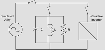
Figure 2. Simulated utility
In order to ensure that interactive inverters will not island, a special test was devised that represents a worst-case combination of possible connected loads (see figure 2). By balancing the reactive contributions from capacitors, inductors and a real load in the form of resistors, a resonant circuit can be created. At present, UL 1741 requires that interactive inverters be capable of detecting this scenario and ceasing their power export within 2 seconds.
The interactive inverter must incorporate an active means to destabilize a resonant load within 2 seconds. This often requires than the unit periodically “bump” its voltage or current output to cause the resonant load to collapse to the point that the voltage or frequency goes out of the normal range indicated in table 1. This, however, leads to another leading utility concern—current distortion.
An example waveform is shown on figure 3. Here it can be seen that the unit briefly surges the output periodically to ensure compliance with the UL 1741 anti-islanding test. The impact of this surge and its contribution to the total harmonic distortion output current waveforms are analyzed according to table 2, which is identical to the requirements of IEEE 519-1992, “Recommended Practices and Requirements for Harmonic Control in Electrical Power Systems.”
Table 2. Harmonic distortion limits for interactive inverters
Odd Harmonics Distortion Limit
3rd through 9th < 4%
11th through 15th < 2%
17th through 21st < 1.5%
23rd through 33rd < 0.6%
above 33rd < 0.3%
Furthermore, the even order harmonics are restricted to 25 percent of the above odd harmonic values. Inverters that are listed must meet the above requirements while operating at 100 percent of their rated power output.
As one might imagine, there are several other testing requirements in UL 1741 to address utility concerns. For instance, interactive inverters cannot inject more than 0.5 percent dc into an ac circuit, must operate at a power-factor of 0.85 or higher, and if the interactive inverter ceases power export due to a utility fault, the unit must remain off-line for 5 minutes after the utility has returned to normal operation.
Currently, a few of these requirements are in the process of change due to the publication of IEEE 1547-2003, “Standard for Interconnecting Distributed Resources with Electric Power Systems.” UL contributed to this development effort and is now under a contract with the Department of Energy to bring UL 1741 into alignment with the IEEE 1547 standard. The IEEE standard represents the efforts of more than 350 people that began work in 1999 to define a utility, manufacturer and user-based consensus standard that covers the requirements for acceptable utility interconnection.
Fire, Shock and Mechanical Evaluation
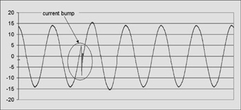
Figure 3
Although much has been said of the utility performance aspects of UL 1741, it is important to know that interactive inverters must also undergo all of the fire, shock and personal injury hazard evaluations that effectively reduce these risks.
Other hazards that are evaluated include installation and mechanical hazards. Units are intentionally mis-wired to determine the safety issues that could occur from improper wiring. Wire bending spaces are examined, as is the general suitability of the enclosure for the intended environment. Also hazards from mounting the unit or its potential to tip over are evaluated. Concurrent with this testing, installation instructions and marking details are studied to ensure that appropriate and code-compliant information is provided to the user. Among other important information, “Utility-Interactive” must always appear on the label of an interactive inverter.
The NEC
From a code perspective, interactive inverters must comply with the requirements of the 2002 NEC Article 705, Interconnected Electric Power Production Sources. Specifically of note are:
1. Disconnecting means in Section 705.21 and the marking requirement of Section 705.22, which is required typically between the alternative energy source and the inverter and between the inverter and the interconnection panel, which is fed from a utility source.
2. Connection of the interactive inverter must be made to the supply-side of installed ground-fault protectors, per Section 705.32.
3. Section 705.40, which requires disconnection of the interactive inverter from the utility upon loss of utility power.
4. Also, Section 705.42 that requires a similar disconnection of the interactive inverter if one phase of a three-phase connection opens.
5. Note that for PV systems with interactive inverters Article 690, Solar Photovoltaic Systems, takes precedent over Article 705.
6. Similarly note that for fuel cell systems, Article 692, Fuel Cell Systems, takes precedent over Article 705.
With regard to PV and fuel cell installations that use an interactive inverter, it is important to note that the typical installation practice is to connect the utility-interactive inverter through a back-fed breaker into an existing load center. NEC Sections 690.64 for PV and 692.64 for fuel cells provide guidelines for how to connect an interactive inverter onto a dedicated branch circuit. The main code concern is to avoid a possible overloading of the load center busbar or conductor rating with the addition of the new alternative energy system supply. Often this means that the main breaker is de-rated by the size of the new supply branch overcurrent protector. Note, however, that dwellings can allow an additional source which brings the panel to 120 percent of its rating per Sections 690.64(B)(2)Exception and 692.65(B)(2)Exception.
The subtle mixing of utility performance concerns into the language of the 2002 NEC 705.40 and 705.42 (above) is an interesting trend that will likely continue as alternative energy projects, and the interactive inverters that make them possible, become more prevalent within the U.S. To help ensure that the trend continues, UL is working hard to ensure that both electrical inspector and utility engineer’s concerns are met with UL 1741 and UL’s listing of utility interactive inverters.
Summary
The utility-interactive inverter is an important key for unlocking future U.S. growth of alternative energy projects. As this equipment has the ability to export energy back to the local utility, it must meet not only the requirements of the electrical inspector, but the utility system protection engineer as well. This bridging of jurisdictional concerns has been incorporated into the standard used to evaluate this equipment, UL 1741, Inverters, Converters and Controllers for Use in Independent Power Systems, and is also evident in the NEC Article 705, Interconnected Electric Power Production Sources. Although the present number of utility-interactive systems is approximately 5,000, growth in wind, solar and fuel cell projects has been impressive. So, the chances are that most inspectors will, at some point in the future, have exposure to this equipment.
To make electrical inspections easier for AHJs, UL has included a list of all distributed generation (DG) product categories in the front of the General Information for Electrical Equipment Directory (the White Book) on page xix. Also, for more information on utility-interactive inverters and distributed generation equipment in general, be sure to visit us on the web athttp://www.ul.com/dge.
Endnotes
1 Price, S., Herig, C., Goldstein, H., Gillette, L., Boedecker, E., and Holihan, J., “U.S. On-Grid Photovoltaic Capacity: A Baseline for the National Energy Modelling System,” National Renewable Energy Laboratory report NREL/CP-620-32104 (May 2002).
2 Data obtained from the National Renewable Energy Laboratory online database available athttp://analysis.nrel.gov/repis/online_access.asp.
3 Geiger, S., and Cropper, M., “Fuel Cell Market Survey: Small Stationary Applications,” Fuel Cell Today (July 2003): online report available atwww.fuelcelltoday.com.
4 Cropper, M., “Fuel Cell Market Survey: Large Stationary Applications,” Fuel Cell Today (September 2003, online report available atwww.fuelcelltoday.com.
5 Qin, Y.C., Mohan, N., West, R. and Bonn, R., “Status and Need of Power Electronics for Photovoltaic Inverters, Sandia National Laboratories,” Sandia National Laboratories report SAND2002-1535 (June 2002): 32.
6 Underwriters Laboratories Inc. Standard for Safety for Inverters, Converters, and Controllers for Use in Independent Power Systems, UL 1741, First Edition (May 7, 1999).
7 Alderfer, R., Eldrige, M., Starrs, T, and Nakarado, G., “Making Connections— Case Studies of Interconnection Barriers and Their Impact on Distributed Power Projects.” National Renewable Energy Laboratory report NREL/SR-200-28053 (May 2000).
8 American Public Power Association. “U.S. Electric Utility Statistics, 2001.” 2003 Annual Directory & Statistical Report (2003): 13. Online report available atwww.APPAnet.org.