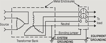
Empirical data indicates that around 80 percent of all electrical interruptions are attributable to ground faults that are a result of an unintentional connection between system conductors and ground. The term grounding is commonly used in the electrical industry to mean both “”equipment grounding”” and “system grounding.” System grounding means the intentional connection of a neutral or phase conductor, either solidly or through an impedance or resistance device, to ground from a source such as transformer, rotating machinery, solar photovoltaic, etc. Figure 1 illustrates the two types of grounding.
System grounding, or the intentional connection of a phase or neutral conductor to earth, is for the purpose of controlling the voltage to earth, or ground, within predictable limits. It also provides for a flow of current that will facilitate overcurrent device operation during an unwanted connection between system conductors and ground (a ground fault).

Figure 1. System versus equipment grounding
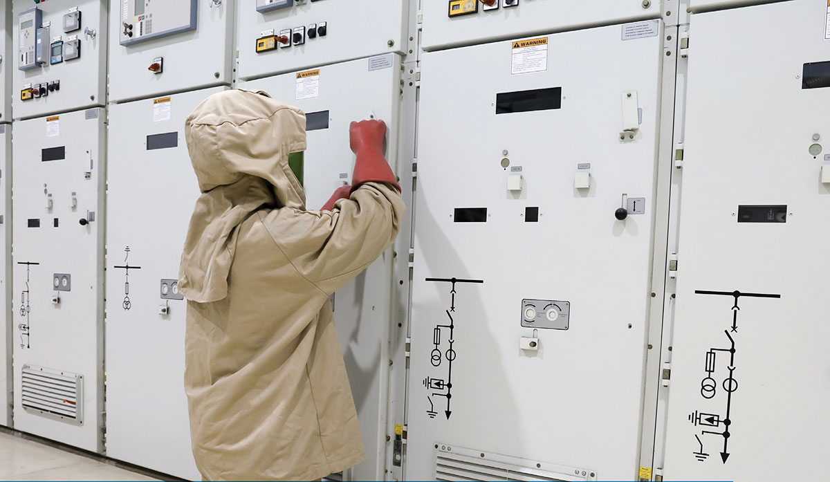
The root cause of this unwanted connection is often a result of insulation breakdown. The energy released from the ground fault can lead to process interruptions, equipment damage and present a fire and explosion risk to personnel (see photo 1). Five to ten arc-flash explosions occur in electric equipment every day according to statistics compiled by CapSchell Inc, a Chicago-based research and consulting firm that specializes in preventing workplace injuries and deaths.
From 1992 to 1999 a single leading industrial insurance company reported 228 losses that were attributed to ground faults with a total cost of US $180 million.

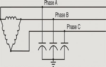
Figure 2. Typical ungrounded system
The same insurance company has stated that they have evaluated the property and business interruption potential as a result of not having ground-fault protection and found it to be significant enough to warrant installation of ground-fault protection. In the winter issue of Pure Power, they went a step further and stated that, “using a high resistance ground system could knock 10% off the price of insurance.”
And yet the majority of industrial facilities continue to operate without adequate ground-fault protection. These establishments typically operate an ungrounded or solidly grounded electrical distribution system, both of which have inherent disadvantages.
An ungrounded system is one in which there is no intentional connection between any of the system conductors and earth ground. However, in any system, a capacitive coupling exists between the system conductors and the adjacent grounded surfaces. Consequently, the “ungrounded system” is, in reality, a “capacitively grounded system” by virtue of the distributed leakage capacitance.
The reasoning behind the prevalence of ungrounded systems in many industrial facilities appears to be historical. Prior to the emergence of high resistance grounding in the late 1980s, the only choice when process continuity was desired was an ungrounded system that allowed for the controlled shutdown for fault repairs at a convenient time and this was of tremendous value to continuous manufacturing processes by reducing production losses, equipment damage and outages.

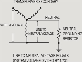
Figure 3. Typical resistance grounded system
However experiences with multiple failures due to arcing ground faults has resulted in a change in philosophy over the use of ungrounded systems and this change is supported in by the Institute of Electrical and Electronic Engineers (IEEE) who in IEEE Standard 242-1986 Recommended Practice for the Protection and Coordination of Industrial and Commercial Power Systems 242-1986 section 7.2.5 offer the following perspective:
“Ungrounded systems offer no advantage over high-resistance grounded systems in terms of continuity of service and have the disadvantages of transient overvoltages, locating the first fault and burndowns from a second ground fault. For these reasons, they are being used less frequently today than high-resistance grounded systems.”
There are many benefits from grounding the electrical distribution system including:
- Reduced magnitude of transient overvoltages
- Simplified ground fault location
- Improved system and equipment fault protection
- Reduced maintenance time and expense
- Greater safety for personnel
- Improved lightning protection
- Reduction in frequency of faults
The choice for many engineers is focused on what grounding technology to use.

Photo 1. The energy released from the ground fault can lead to process interruptions, equipment damage and present a fire and explosion risk to personnel
A solidly grounded system is one in which one conductor of the system has been intentionally connected to earth ground with a conductor having no intentional impedance and this partially reduces the problem of transient overvoltages found on the ungrounded system.
While solidly grounded systems are an improvement over ungrounded systems, and speed the location of faults, they lack the current-limiting ability of resistance grounding and the extra protection this provides. The destructive nature of arcing ground faults in solidly grounded systems is well known and documented and are caused by the energy dissipated in the fault. A measure of this energy can be obtained from the estimate of kilowatt-cycles dissipated in the arc:
Kilowatt cycles = V x I x Time/1000.
In the same IEEE Standard as referenced above, section 7.2.2 states that: “one disadvantage of the solidly grounded 480-V system involves the high magnitude of ground-fault currents that can occur, and the destructive nature of arcing ground faults.”
Since the vast majority of arcing faults start their life as single-phase faults, the key to reducing their impact is to use technology that either significantly reduces the fault current level thereby reducing the magnitude of the arc hazard and/or using technology that prevents transient overvoltages that can lead to single-phase faults escalating into arcing faults.
The answer in both cases is high resistance grounding, as recognized in the Canadian Electrical Code section 10-1100, and the National Electrical Code section 250.36.
High resistance grounding of the neutral limits the ground-fault current to a very low level (typically from 1 to 10 amps) and this is achieved by connecting a current-limiting resistor between the neutral of the transformer secondary and the earth ground and is used on low-voltage systems of 600 volts or less, under 3000 amp. By limiting the ground-fault current, the fault can be tolerated on the system until it can be located, and then isolated or removed at a convenient time.
In tests, damaging voltage transients measured on a 480-volt ungrounded system were eliminated once the circuit was converted to high resistance grounded.
With respect to the magnitude of fault current, the energy or I 2 t value for a 1 amp fault is 1/ 1,000,000 of a 1000 amp fault assuming an equal amount of time.
The National Electric Code allows a fault level of 1200 amps for one second on a solidly grounded system before a circuit must trip; however, in practice fault levels in excess of 20,000 amps are common for a short period of time.
In IEEE Standard 142-1991 Recommended Practice for Grounding of Industrial and Commercial Power Systems the following perspective is outlined in section 1.4.3:
“The reasons for limiting the current by resistance grounding may be one or more of the following.
1) To reduce burning and melting effects in faulted electric equipment, such as switchgear, transformers, cables and rotating machines.
2) To reduce mechanical stresses in circuits and apparatus-carrying fault currents.
3) To reduce electric-shock hazards to personnel caused by stray ground-fault currents in the ground return path.
4) To reduce the arc-blast hazard to personnel who may have accidentally caused or who happen to be in close proximity to the ground fault.
5) To reduce the momentary line-voltage dip occasioned by the occurrence and clearing of a ground fault.
6) To secure control of transient overvoltages while at the same time avoiding the shutdown of a faulty circuit on the occurrence of the first ground fault.”
The judicious use of high resistance grounding facilitates process continuity, reduces equipment damage, allows for predictive maintenance, reduces shock hazard and can minimize the impact of arc blast hazards.


Find Us on Socials