In part 1, I described current as being the motion of electrons from one atom to the next within a material. A material’s ability to conduct current is a function of its ability to pass on electrons. All materials conduct current to some degree. Materials that resist the passing on of electrons are called insulators. Materials that put up very little resistance to the passing on of electrons are called conductors.
Ohm’s Law and Electrical Resistance
When we speak of the electrical resistance of a material, we are referring to the resistance of the material to pass on electrons. Electrical resistance is symbolized by the letter R for calculation purposes and is measured in ohms (abbreviated with the Greek letter ). To measure the resistance of a material, we apply a voltage to the material and measure how much current flows as a result of the voltage. The resistance is then calculated by dividing the voltage V by the current I.
For calculation purposes, the letter I is commonly used to represent the current: R = V / I. This relationship between current, voltage and resistance is known as Ohm’s Law because it was discovered experimentally by the German physicist Georg Simon Ohm around 1840. If we multiply both sides of the equation by I, we change the form of the equation to V = I x R. If we then divide both sides of the equation by R, we change the form of the equation to I = V / R. Now we have Ohm’s Law in three forms. I numbered each equation for future reference.
V = I x R (1)
I = V / R (2)
R = V / I (3)
If we know the value of any two of the three elements—current, voltage or resistance—we can calculate the third. Later, I will crank through a few simple examples and talk more about resistance, but I first want to touch on power.
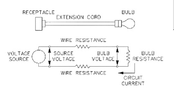
Figure 1
Power
In mechanical devices like internal combustion engines, power is the force the engine pushes on an object times the distance the object moves divided by the time it takes the object to move that distance. Power is symbolized by the letter P for calculation purposes. Mechanical power is often measured in horsepower (abbreviated hp). For example, if the force necessary to keep a car moving at 30 miles per hour (44 ft./second) is 300 pounds, then the amount of power necessary is 300 lb. x 44 ft./sec.= 13,200 ft.-lb./sec. To convert to horsepower, we divide by 550. The power necessary to keep the car moving is 13,200 / 550 = 24 horsepower. In electrical devices, power is measured in watts (abbreviated W). One horsepower equals 746 watts. If a one horsepower electric motor were 100 percent efficient, it would use 746 watts of power when delivering one horsepower of power. When the electrons move from one atom to another atom within a conductor, i.e., when current flows in a wire, heat is generated within the wire because of the passing on of the electrons. The power generated by the wire in the form of heat is the voltage across the wire times the current flowing in the wire: P = V x I. Within an incandescent light bulb, there is a small piece of wire made out of tungsten. Because of its very high melting temperature (3380°C), tungsten works very well as a filament in light bulbs. If a light bulb is rated at sixty watts, that is the amount of power it uses when operated at its rated voltage. How much current does a sixty-watt light bulb draw when operating at 120 volts? If we divide both sides of the above equation by V, we change the form of the equation to I = P / V. Using this equation, we can calculate the current flowing in the light bulb. I = 60 W / 120 V = 0.5 A. To calculate the resistance of the filament, we combine the equations P = V x I and V = I x R, we get P = I 2 x R. If we divide both sides of the equation by I 2 we change the form of the equation to R = P / I 2. Using this equation, the resistance of the bulb filament is 60 W / (0.5 A x 0.5 A) = 240 W. Likewise, if we combine equations P = V x I and I = V / R, we get P = V 2 / R. If we multiply both sides of the equation by R and divide both sides of the equation by P we change the form of the equation to R = V 2 / P. Using this equation, the resistance of the bulb filament is (120 V x 120 V) / 60 W = 240 W. Solving for V and I in the above equations, we create two additional equations. Now we have nine power equations relating power, voltage, current and resistance. Using these equations and Ohm’s Law, if we know any two elements, we can calculate the other two.
P=VxI(4)
V=P/I(5)
I=P /V(6)
P=I2xR(7)
R=P/I2(8)
I= square root (P/R) (9)
P=V2/ R(10)
R=V2/P(11)
V= square root (RxP) (12)
Standard Wire Sizes
Single strand wire sizes are identified by American Wire Gauge (AWG). The higher the gauge, the smaller the wire. Typical house wiring for receptacles is 14 AWG copper. 14 AWG has a diameter of 0.06408 inches. The next larger size after 1 AWG is 0 AWG referred to as “one aught”1 and written as 1/0 AWG. The next larger size above 1/0 AWG is 00 AWG referred to as “”two aught”” and written as 2/0 AWG. The largest wire is 4/0 AWG, 0.4600 inches in diameter. I will talk about larger and multiple strand wires later.
Example Calculations
Now that we have a series of equations relating power, voltage, current and resistance, I want to crank through some simple example calculations.
Problem 1:I want to operate a 60-watt light bulb temporarily in a chicken coop 100 feet from my house to keep some chicks warm at night. We will assume the outside air temperature is constant at 20°C (68°F). I have a 100-foot extension cord with 18 AWG copper wire. What voltage do I need at the house receptacle to insure the voltage at the bulb is 120 V? The circuit diagram looks like figure 1.
The resistance of the 18 AWG copper wire at 20°C is 6.39W/ 1000 ft per manufacturer’s data. Since the cord is only 100 feet long, the resistance of the wire is one tenth of 6.39 or 0.639W. The resistance of the 60-watt bulb operating at 120 volts is 240Was calculated previously. Note that the amount of power the bulb uses and the light output of bulb vary with operating voltage. If the bulb voltage is below 120 V, the bulb uses less power, the light output is reduced and the life of the bulb increases. Likewise, if the voltage is greater than 120 volts, the bulb uses more power, the light output is greater and life of the bulb decreases.
The receptacle at the house is the source of EMF (voltage). How much current is flowing in the circuit? We know that the voltage across the bulb is 120 volts and the power the bulb is using is 60 watts. From this information, we can calculate the current in the circuit using equation (6) I = P / V = 60W/ 120 V = 0.5 A. If the bulb were connected at the source receptacle, the source voltage and the bulb voltage would be the same. In this example, the bulb is connected to the source receptacle by a 100-foot extension cord. The resistance of the extension cord reduces the voltage that gets to the bulb. This reduction in voltage is called voltage drop.
Since we know the resistance of the extension cord and how much current is flowing in the extension cord, we can calculate the voltage drop using equation (1) V = I circuit x R extension cord = 0.5 A x 0.639W= 0.3195 V. This is the voltage drop in just one wire of the extension cord. There is also voltage drop in the other wire so we have to multiply the voltage drop times two. The total voltage drop in the extension cord is 2 x 0.3195 V = 0.639 V. This voltage drop is quite low because the current is low. If we were trying to use a 1500 W electric heater at the end of the same extension cord to heat the entire chicken coop, the voltage drop would be so high the heater would produce much less heat. For the light bulb circuit to deliver 120 volts to the bulb, the source voltage will have to be 120 V plus the voltage drop in the extension cord or 120.639 V.
Problem 2:Let’s consider the problem of heating the entire chicken coop with a 1500Welectric heater at the end of the same extension cord. Note that the nameplate rating on the heater is 1500Wat 120 volts. When the voltage is lower than 120 volts, the heat output of the heater goes down. When the voltage is above 120 volts, the heat output goes up. What source voltage do we need at the house so that the heater gets 120 volts? We can calculate the current the heater draws using equation (6) I = P / V = 1500W/ 120 V = 12.5 A.
We can calculate the voltage drop in the extension cord using equation (1) V = I circuit x R extension cord = 12.5 A. x 0.639W= 7.9875 V. Again the voltage drop is in both wires of the extension cord so we have to multiply by two. The total voltage drop = 2 x 7.9875 = 15.975 V. In this case, the source voltage would have to be 120 V + 15.975 V = 135.975 to maintain the heater voltage at 120 V. I wired up the above example in my lab with the source voltage at 120 V. With the 100 foot extension cord, the voltage at the heater was only 105.1 V and the circuit current was 10.5 A.
Using equation (4) P = V x I, the amount of power the heater was producing was only 105.1 V x 10.5 A = 1103.55W. Note that the reduced voltage at the heater greatly reduces the heat output of the heater. The voltage drop in the extension cord was 120 V – 105.1 V = 14.9 V. Using equation (3) R = V / R, the resistance of the extension cord wire is 7.45 V / 10.5 A = 0.709W. I used half the voltage drop in the equation because half the voltage drop is in each wire. Note that this resistance is higher than the manufacturer’s data. One difference might be because the manufacturer’s data was at 20°C (68°F). When I did the test, the temperature in the room was 80°F and this test was not the first one I did with the extension cord. You will recall that the resistance of the wire produces heat.
That heat gradually raises the temperature of the wire. As the temperature increases, the resistance of the wire increases. After several tests or after running one test for several minutes, the wire within the extension cord may be considerably hotter than 68°F. Using equation (7) we can calculate the amount of heat being produced by each wire of the extension cord. P = I 2 x R = 10.5 A x 10.5 A x 0.709W= 78.16W. The total heat produced by the extension cord is two times that produced by each wire or 2 x 78.16W= 156.32W. This type of wasted power is called loss. Not only is it important to use adequate wire size to insure the heater gets the correct voltage and produces the expected amount of heat, it is also important to reduce the losses. In this example, the total power being used by the circuit is 1103.55W+ 156.32W= 1259.87W. Only 1103.55Wor 87.6 % is being used where we want it in the chicken coop. The other 12.4% is heating up the back yard. If we left the circuit running for several hours, the heating of the extension cord might eventually cause the wire to melt and start a fire. Note that the 15 amp fuse or breaker that protects the 14 AWG copper house wiring will not protect the 18 AWG extension cord. That’s another story I will eventually get to. If I had used an extension cord made with 12 AWG copper wire (1.59W/ 1000 feet), the voltage drop in the extension cord would only be 3.975 volts and the heat loss associated with the extension cord would only be 49.68W.
1Aught is a Middle English word meaning “a cipher; zero.” It is pronounced “ôt.”