Inspectors are more and more frequently faced with permitting or inspecting PV systems as these systems proliferate throughout the country due to increasing regional financial incentive programs. Photovoltaic power is a relatively young technology and industry. While well-qualified people are installing many excellent, code-compliant PV systems, others are designing and installing these systems with little or no prior experience with electrical systems. Unfortunately, as financial incentives continue and even increase, more unqualified people are installing these systems. The electrical inspector, through the permitting and inspection process, can help the PV industry focus on the design and installation of safe, code-compliant PV systems. Inspector involvement early in the process often proves beneficial to all.
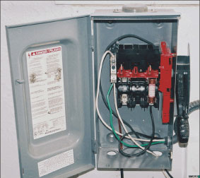
Photo 1. Double lugging and worse are common in PV installations
The information below will help the inspector determine if the basic design of a PV system meets the specific requirements of the National Electrical Code as outlined in Article 690 and in other sections of the Code. Additional information will be provided to highlight areas that should receive special attention during the inspection. Inspectors need to be at least as well informed, if not better informed, than the designers and installers of these systems.
The Permit
As a part-time inspector and plan reviewer (for utility companies and municipalities who require code-compliant PV systems), I always require that the vendor/installer provide a neat, legible system diagram, a list of the conductors and parts used (with model numbers), and the calculations used for conductor and conduit sizing and overcurrent device rating. Although I don’t require engineering drawings, or even CAD drawings, unreadable, messy scribbles on the backs of envelopes are rejected. Since both inspectors and installers have not done thousands of PV systems, the inspector should accept nothing less.
Conductor Types
Module junction box temperatures may be 30–35°C higher than ambient temperatures, and 75–80°C temperatures are not uncommon. The conductor types selected for connection to the PV modules should be rated for wet, 90°C conditions. In conduit, these are normally THHN/THWN-2 or RHW-2 types. If in free air, as allowed by the Code, the conductors most commonly used are USE-2, and if these are to be also run in conduit, they should be USE-2/RHW-2—particularly if the conduit is inside the building. [See “Perspectives on PV” in the July/August 2004 issue of the IAEI News for more information.]
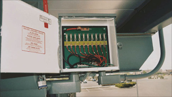
Photo 2. Improper color codes and exposed, energized bus bars
Conductors in outside conduits or in PV combiners or junction boxes exposed to the sun may be operating at 17°C or higher than the ambient temperature [see the fine print note No. 2 in Section 310.10 in the 2005 NEC]. In PV systems we suggest adding 20°C to the ambient temperature to accommodate the temperature rise in aging, dull-colored conduits. Again, this usually dictates the use of wet rated conductors with temperature ratings of 90°C, although some installations in cold climates might squeeze by with 75°C insulated conductors.
Currents, Cables, and Overcurrent Devices
The process for calculating cable sizes for PV systems in the Code is somewhat complex, particularly when conditions of use are applied that include temperature deratings and conduit fill as well as the temperature limitations of the terminals of overcurrent devices. See Appendix I of the author’s PV Power Systems and the National Electrical Code: Suggested Practices (available free as a download—see endnote1). A slightly abbreviated version is presented here.
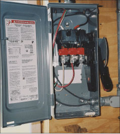
Photo 3. Grounded conductor improperly switched
Due to the unique characteristics of solar energy and PV modules, worst-case currents are always used and are considered continuous [see “”Perspectives on PV”” in the July/August 2004 IAEI News]. In any PV source circuit (one module or a series connected string of modules) the individual module short-circuit current (Isc) is multiplied by 1.56 to get the basic conductor ampacity rating (at 30°C) and the overcurrent device (where required) to protect this conductor and the internal module conductors. Temperature correction factors, for the conductors connected to the modules, of either 65°C (cooling air to the back of the modules—4 inches or more of space) or 75°C (no cooling air—less than 4 inches of space) are applied to the 30°C ampacity.
Overcurrent devices (where required) are installed electrically and physically away from the modules in combiner circuit boxes where the PV source circuits are combined in parallel. If the combiner boxes are exposed to sunlight and ambient temperatures over 40°C (104°F), then it is likely that the overcurrent devices will be exposed to temperatures in excess of their normal 40°C maximum. In practice, a 10–15 percent derating should be applied to the overcurrent device rating and then it should be verified that it would still protect the conductor.
When dealing with temperature deratings on 90°C conductors connected to overcurrent devices with terminals rated for conductors operating at no more that 75°C or possibly even 60°C, that 1.56 x Isc calculated current must be below the 75°C (or 60°C) ampacity values for the conductor size being used [see 110.14(C)].
When PV module source circuits are paralleled in PV combiners, then the short-circuit currents of the paralleled circuits sum together, and new conductors and overcurrent devices must be selected to handle the increased currents.
The voltage rating of conductors, overcurrent devices, and disconnects must be based on the maximum system voltage, which is the sum of the open-circuit voltage (Voc) of all modules connected in series times a temperature dependent factor found in NEC Table 690.7. A factor of 1.25 can be used for any system that is installed in locations where the record low temperature is no lower than -40°C (-40°F).
Disconnects
On utility-interactive PV systems, disconnects are generally required for the main PV circuit input to the inverter and the inverter ac output (which may be a backfed breaker in a load center). The addition of batteries in some systems will necessitate additional disconnects. Most utilities require an outside, visible blade, lockable disconnect between the ac output of a PV system and the point where that output connects to the utility. While not a Code requirement, it must be installed in a code-compliant manner.
The disconnect must have a rating of 1.56 Isc at that point, and must have a voltage rating and be connected in a manner consistent with the maximum system voltage.
Inverter AC Outputs
The connection to the utility must meet the requirements of NEC 690.64(B)(2). In residential systems, this section of the Code will allow a relatively small PV system to backfeed the residential load center. In commercial systems, either the size of the load center must be adjusted or a second service entrance must be added to accommodate the PV system.
The Inspection
Good workmanship
For some reason, even experienced electricians frequently forget to use good workmanship when installing PV systems. In all cases, conduit should be fastened to structures for protection against wind and ice loading. Modules and mounting racks as well as other equipment should be firmly mounted to structures in a manner that will resist environmental stresses of sunlight, wind, and rain at the very least. Areas of the country subject to earthquakes or hurricanes will require specialized, more rugged installations.
Double lugging and worse are common in PV installations (see photo 1 for an example).
Grounding
Grounded conductors, both ac (neutral) and dc (negative), should be white or marked white and should never be interrupted by a switch pole, fuse, or circuit breaker —particularly on dc source circuits from the PV modules (see photos 2 and 3).
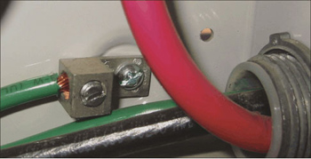
Grounding of module frames, combiner enclosures and disconnects in the dc circuits is important because they may operate up to 600 volts in commonly installed systems. No sheet metal or “”tech”” screws should be used to ground disconnect enclosures with tin-plated aluminum lugs; proper grounding/ground bar kits should be used (see photo 4). [See “Perspectives on PV” in the September/October 2004 issue of the IAEI News for more details on grounding PV modules.]
When metal conduit has been used, proper bonding of the conduit to the enclosures should be verified, particularly when the dc PV voltages are above 250 volts.
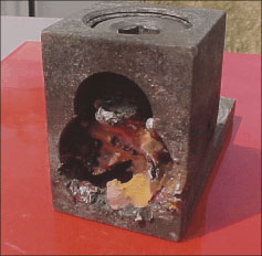
Photo 5. Fine stranded cable, improperly terminated
The ac portion of most PV systems should have only one neutral-to-ground bond, and that bond will frequently be in the ac load center for the system. Since the inverter uses a transformer that isolates the dc grounded conductor from the ac grounded conductor, the dc negative should also have a single bond to ground. Many utility-interactive inverters make this dc bond internally and there should be a separate dc grounding electrode conductor routed to either a dc grounding system or to the ac grounding system. Any roof top PV system on a dwelling should have a Section 690.5 ground-fault protection system and these may be either external to the inverter or built in. The grounding electrode conductor will be connected to this device when it is external to the inverter.
Overcurrent Protection
Overcurrent devices in disconnect enclosures and PV combiners located in readily accessible locations that have exposed internal circuits should be accessible only by qualified persons. If these devices have exposed internal terminals and/or bus bars that could be energized when opened, the covers should require at least a tool for access. Although not required (yet) by the Code or UL Standards, these devices would benefit from a warning label—on the outside: “”Warning: Electric Shock—No User Serviceable Parts Inside”” (see photo 2).
Disconnects
The location of the main PV disconnect must comply with 690.14, and unless the PV source circuit conductors are installed in metallic raceways, they must remain outside the structure until that first, readily accessible disconnect is reached (see 690.31(E) in the 2005 Code). Although the NEC allows this disconnect to be either outside the structure or immediately inside the structure at the point of first penetration, the PV disconnect is normally mounted in the same manner as the ac service disconnect for the particular jurisdiction.
On the system with batteries and larger systems that use larger conductors (e.g., 2/0 AWG and above), the inspector should verify that fine stranded cables (where used) are properly terminated with connectors and terminals listed for use with such cables (see photo 5).
Summary
Photovoltaic power systems have the potential to produce significant amounts of energy for many years. The well-informed inspector can make a significant contribution to the safety, quality, durability, and even performance of these systems. Compliance with the requirements of the NEC and the recognition that the Code gives minimum requirements should result in a safe, durable system, particularly if these minimums are exceeded. A well-qualified team that includes the designer, installer and the inspector will help ensure that these systems remain safe for their entire life.
For Additional Information
If this article has raised questions, do not hesitate to contact the author by phone or e-mail. E-mail: jwiles@nmsu.edu. Phone: 505-646-6105.
1 A PV Systems Inspector/Installer Checklist will be sent via e-mail to those requesting it. A draft copy of the 143-page, 2005 edition of the Photovoltaic Power Systems and the National Electrical Code: Suggested Practices, published by Sandia National Laboratories and written by the author, may be downloaded from this web site (http://www.nmsu.edu/~tdi/roswell-8opt.pdf.) The Southwest Technology Development web site (http://www.nmsu.edu/~tdi) maintains all copies of the “”Code Corner Columns”” written by the author and published in Home Power Magazine over the last ten years. Copies of previous “”Perspectives on PV”” are also available on this web site.
The author makes 6–8 hour presentations on “”PV Systems and the NEC”” to groups of 40 or more inspectors, electricians, electrical contractors, and PV professionals for a very nominal cost on an as-requested basis.