
Have you ever been confused about what the markings on circuit breakers mean? Understanding the markings on electrical equipment is a fundamental need to ensure a safe and reliable electrical installation. Circuit breaker marking requirements are established by the requirements found in the NEC and the UL 489 product standard. This article will discuss the most common markings and where they can be found.
The UL 489 product standard for Molded Case Circuit Breakers specifies the information to be marked on circuit breakers and where it is to be located, so let’s discuss what information needs to be marked on the circuit breaker and the location where you will find those markings. Keep in mind the UL® standard specifies minimum requirements. Circuit breaker manufacturers may provide additional information or provide information in a more convenient location.
Markings Visible without Removing Trims or Covers
UL 489 requires that some markings be visible without removing trims or covers. This location is typically referred to as the handle escutcheon (see photo 1).
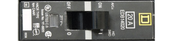
Photo 1. Markings visible with trims or covers in place
Markings Visible with Trims or Covers Removed
UL 489 requires other markings be visible on an installed circuit breaker with trims or covers removed. This location is typically referred to as the face of the circuit breaker (see photos 2, 3, 4).
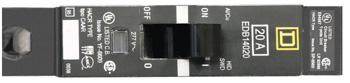
Photo 2. Markings visible with trims or covers removed
Other markings which should be visible with trims or covers removed are:
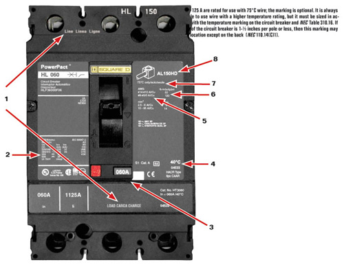
Photo 3. Markings visible with trims or covers removed
Independent trip –
Multi-pole circuit breakers are constructed with either a common trip, where all poles are mechanically tripped when one of the poles trips, or an independent trip construction where only the pole that is involved with the overcurrent condition trips. If a 2-pole circuit breaker does not have an internal common trip feature, then it must be marked “Independent Trip” or “No Common Trip.” NEC 240.20(B) is the foundational requirement for a common trip function in a circuit breaker; however, it also goes on to explain where independent trip is permitted.
For Replacement Use Only not-CTL –The Class CTL (circuit limiting) panelboard has only been in existence for about 25 years, even though the lighting and appliance branch circuit panelboard has been in the NEC for decades. CTL panelboards have a rejection means designed to reject more than the appropriate number of circuit breakers that can be installed in the panel. The marking “For replacement Use Only Not CTL Assemblies” means that the circuit breaker does not have CTL rejection provisions and is intended for replacement in older equipment pre-dating the CTL requirements for circuit breakers and panelboards. Circuit breakers with this designation should not be installed in a panelboard marked “Class CTL Panelboard” since that would be a violation of the listing of the assembly [NEC 110.3(B)].
Markings Found in Other Locations
The markings we will discuss below may appear in any location except the back of the circuit breaker. These markings include:
40°C –This marking indicates the maximum ambient temperature in which the circuit breaker can be applied at its marked ampere rating without rerating the ampacity of the circuit breaker. This marking is required for thermal-magnetic circuit breakers and is optional for electronic trip circuit breakers unless they are only suitable for a 25°C ambient, in which case they must be marked 25°C. When the ambient temperature rises above 40°C, the designer may need to consult the manufacturer to obtain rerating information (see item 4 in photo 3).
Class CTL –Circuit breakers marked Class CTL have a rejection means designed into the circuit breaker. Class CTL panelboards or assemblies, in conjunction with Class CTL circuit breakers, prevent more circuit breaker poles from being installed than the number for which the equipment is rated.
HACR type –This marking indicates the circuit breaker is suitable for use with the group motor installations typically found in heating, air conditioning and refrigeration equipment. TheNEC2005 no longer has this marking requirement. The electrical industry determined that circuit breakers are considered suitable for use with such equipment without any further testing, therefore, the HACR marking is no longer required on air conditioning and refrigeration equipment or on circuit breakers for use in these applications. The requirement for this marking has also been removed from the UL 1995 product standard for HVAC equipment (see item 3 in photo 1).
Maximum wire size –Circuit breakers are typically marked with a wire range, however that marking is not mandatory. If the circuit breaker cannot accept the next larger wire size required for the ampere rating, then the maximum wire size must be marked in any location except the back (see item 5 in photo 3).
Separately shipped connectors –If connectors are not factory installed on a circuit breaker, then it must be marked with the proper connectors or terminal kits required in any location except the back (see item 8 in photo 3).
Ground-Fault Protection for People
The GFCI function, as part of a circuit breaker, provides ground-fault protection for people and has a number of unique marking and instruction requirements.
Test function –The GFCI has a test function that requires action upon installation and on a monthly basis. GFCI circuit breakers must have a test button or switch that must be labeled in a location accessible without removing trims or covers in order to facilitate monthly testing.
“Class A” marking –A “Class A” ground-fault device is intended to protect people. The Class A marking indicates that the trip threshold of the GFCI is between 4 mA and 6 mA. This marking may be in any location except the back.
Instructions –All GFCI circuit breakers must include instructions for the installer plus instructions on the use of the test function. A hangtag or self-adhesive label must also be provided, instructing the user to test the GFCI at least monthly. Inspectors should check to see that the tag or label has been properly installed.
Ground-Fault Protection for Equipment
Circuit breakers may also include a ground-fault protection for equipment (GFPE) function that, like GFCIs, has a number of unique marking and instruction requirements.
Test function –GFPE circuit breakers may have a test button or switch that may be labeled in a location accessible without removing trims or covers in order to facilitate testing.
Trip level –GFPE circuit breakers must be marked with their trip threshold in milliamperes in a location accessible without removing trims or covers.
Instructions –All GFPE circuit breakers must include instructions for the installer.
Arc-Fault Protection
Circuit breakers may also include arc-fault protection (AFCI) that, like GFCIs, also has a number of unique marking and instruction requirements.
Device identification –AFCIs must also be identified appropriately. Branch/feeder or Combination type AFCIs must be so marked in a location visible when the trims or covers are removed. This is an important marking to note as we move into 2008, asNEC-2005 requires Combination AFCIs in bedrooms effective January 1, 2008 (NEC 210.12).
Test function –AFCI circuit breakers must have a test button or switch that must be labeled in a location accessible without removing trims or covers in order to facilitate testing.
Instructions –All AFCI circuit breakers must include instructions for the installer.
Circuit Breaker Markings Ensure a Safe Electrical Installation
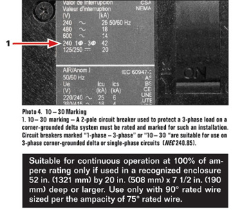
Photo 4. Special marking
So why are all of these markings on circuit breakers? Without them, it would be nearly impossible to install or inspect an installation for the appropriate performance ratings and fundamental electrical connections. When designing or completing an installation, key items to review are:
1. Are the voltage, continuous current, and interrupting ratings appropriate for the application?
2. Does the application require SWD or HID ratings?
3. Is the wire type and size appropriate for the circuit breaker?
4. Is the circuit breaker suitable for the equipment in which it is installed? Have other protective functions such as GFCI or AFCI been provided as required by the NEC?
5. Is the temperature rating of the circuit breaker suitable for the application?
The UL Marking Guide for Molded Case Circuit Breakers is a valuable resource to understand circuit breaker markings that may further explain these and other markings in detail. If you have questions about CB markings not answered here, consult the Marking Guide or the manufacturer to assist in an NEC-compliant installation.