Typically, when length is a factor in the installation, so is voltage drop. A variety of installations may involve feeders or branch circuits of considerable length. These include such installations as industrial plants; airports; tollway, highway, turnpike or street lighting; electrically controlled irrigation machines (also known as center pivot irrigation machines); installations on docks, marinas, or boatyards; farms or ranches; and commercial, residential, or governmental structures. Electrical designers and installers as a whole are generally aware of the requirements in 210.19(A)(1), and fine print note (FPN) No. 4 that provides explanatory material relating to voltage drop for feeders and branch circuits and suggests the maximum percentage of voltage drop which will provide “reasonable efficiency of operation,” should not exceed 5% at the farthest outlet where power is required. Some regard and apply the information as a requirement of the Code, and others may ignore it because they figure, Hey, it’s not mandatory text, so it’s no big deal if I do it or not.
Generally, switchboards and panelboards will function with voltages that are slightly lower than standard nominal ratings with no ill effects to them. Utilization equipment, however, such as lighting, computer-data processing equipment, electronic equipment, and motors may malfunction or be severely damaged by under-voltage conditions. One important thing to consider is the manufacturer’s instructions that are included with the listing and labeling of the product. Even though both 210.19(A)(1) FPN No. 4 and 215.2(3) FPN No. 2 suggest percentages for maximum allowable voltage drop which will provide reasonable efficiency of operation for utilization equipment, Section 110.3(B) requires all listed and labeled electrical equipment to be installed and used in accordance with the manufacturer’s instructions included with the product’s listing and labeling. Nearly all electrical equipment and materials that are installed and used today are listed, labeled, and include installation instructions.
For example, in an outdoor area lighting installation such as those at sports complexes and so forth, luminaires (lighting fixtures) rated for operation at 240 volts ac, nominal, may have manufacturer’s instructions included with the product that permit an operating voltage of no less than 228 volts for proper operation. A 5% voltage drop from 240 volts nominal is 228 volts (240 V x .95 = 228 V), and meets the minimum voltage allowed per the manufacturer. A drop in voltage of more than 5% will cause the luminaires to malfunction. Utility system distribution voltages typically are regulated to be kept within a certain bandwidth, normally plus or minus 2% of nominal system voltage for the end user. In some parts of the country, utilities may generate and distribute voltages that may be as much as 4% higher than the nominal system voltage (240 V x 1.04 = 249.6 V). This slight variation of higher voltage is favorable to the designer/installer of electrical systems, helps with voltage-drop concerns, and will generally not harm utilization equipment, but cannot be counted on. It is wise to install electrical systems to a worst-case scenario and account for some slight drop in voltage, as distribution system loads may increase and power source feed locations may change in time. The point to remember is that electrical installations must meet at least the minimum requirements of the Code, and 110.3(B) is definitely one of the requirements that cannot be ignored.
Enter Article 250
Sizing electrical ungrounded (hot) and grounded (neutral) conductors for voltage drop is a necessity for the proper functioning of electrical equipment and as a requirement of the Code. However, equipment grounding conductors must also be considered for a properly functioning and code-compliant feeder or branch-circuit installation. These conductors are an essential part of a safe electrical installation, as they protect people and property from injury or damage.
Proper Sizing of Equipment Grounding Conductors for Voltage-Drop Situations
Of course, equipment grounding conductors (EGCs) may be installed in the form of busbars, metal raceways, or be considered as the outer metal sheath of cables of one type or another in accordance with 250.118, Types of Equipment Grounding Conductors, and other applicable Code rules. EGCs also may be in the form of solid or stranded, insulated, covered or bare wire type conductors. For simplicity and illustration, wire type conductors will be addressed in this article.
Generally, with few exceptions, all feeders and branch circuits require some sort of EGC. Feeders and branch circuits of extended length are required to have an EGC that will perform per 250.4(A)(5), and qualify as a “permanent, low-impedance circuit facilitating the operation of the overcurrent protective device or ground detector for high-impedance grounded systems.” Safety hazards to life and property are created when feeders or branch circuits are run a long distance and the EGCs are undersized when a ground fault occurs a long distance from the source of power. The overcurrent protective device may not see nor clear the fault, and the ground-fault current may endanger persons or damage property.
When ungrounded and grounded (neutral) conductors are run a long distance and are required to be increased a percentage above the standard size conductor in order to function properly, per Section 110.3(B), manufacturers’ or listing agencies’ instructions, EGCs must be increased in size also as they may be needed and must be ready to carry fault current to open an overcurrent device [also see 250.122(B)].
The minimum sizes for EGCs are found in NEC Table 250.122. The note at the bottom of the table requires that “where necessary to comply with 250.4(A)(5) or (B)(4), the equipment grounding conductor shall be sized larger than given in this table.” Section 250.122(F) applies where conductors are run in parallel. Individual EGCs and those installed in parallel must comply with the note at the bottom of Table 250.122.
Sample Voltage-Drop Calculation
This example is given as an illustration to resemble a real-world voltage drop scenario, and emphasize some items to consider when long runs of electrical feeders or branch circuits may be necessary or cannot be avoided. Installations including all conductors within the same cable(s) are commonly used; however, raceways are discussed here; though for simplicity, raceway sizes are not mentioned.
Obviously, as conductor sizes are increased, raceway sizes may need to be increased. Voltage drop for branch circuits and cable installations is reserved for another article, though most information here would apply. The load for the feeder has already been calculated per Article 220. Other real-world concerns such as customer preference, the cost and availability of conductors and electrical equipment such as large transformers, or installing a high-voltage feeder using overhead spans of smaller conductors are all factors that designers and installers must consider when designing any installation.

Figure 1. 2000-amp, 208Y/120V-feeder, distance = 1500 feet long
Example: A proposed 2000-amp 208Y/120 V feeder will be 750 feet long (for a total length of 1500 feet to the load and back) in its maximum length (including all branch circuits); have 5) 600 kcmil copper conductors per phase installed in non-metallic conduit (5 x 420 amperes = 2100 amperes), include a 1/0 grounded (neutral) conductor in each raceway (the neutral load has been sized per 220.61 at 620 amperes), (5 x 150 amperes = 750 amperes), and a required minimum equipment grounding conductor size of 250 kcmil to be installed in each raceway per Table 250.122 and Section 250.122(F). For our example, all conductors are copper, and their ampacities are taken from the 75°C column of Table 310.16 for THWN conductors (see figure 1).
The questions are, Are all conductors properly sized to account for voltage drop? and Are the proposed equipment grounding conductors adequate to facilitate the operation of the overcurrent device per the requirements in 250.4(A)(5)?
Utilizing the voltage drop/circular mil formula found on page 136 of volume 2 of Ferm’s Fast Finder, 2005 edition, for three-phase circuits for the ungrounded conductors:
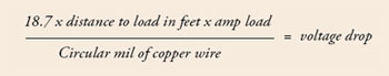
Formula 1
(18.7 is known as the “K” factor, a value assigned for the resistance of a conductor at a certain temperature per foot rated to the circular mil size. Other examples of the use and calculation of the K factor are given in Ferm’s Fast Finder).

Formula 2
If the wire size of the ungrounded conductors is increased to 700 kcmil each:

Formula 3
If the wire size of the ungrounded conductors is increased to 750 kcmil each:

Formula 4
If the wire size of the ungrounded conductors is increased to 800 kcmil each:

Formula 5
If the wire size of the ungrounded conductors is increased to 900 kcmil each:

Formula 6
If the wire size of the ungrounded conductors is increased to 1,000 kcmil each:

Formula 7
If the wire size of the ungrounded conductors is increased to 1,250 kcmil each:

Formula 8
The grounded (neutral) 1/0 copper THWN conductors are rated at 150 amperes, and are 105,600 cm in size per chapter 9, Table 8, Conductor Properties. 105,600 cm x 2.08 (208%) = 219,648 cm, which is not a standard size conductor. The closest size above that value is 250 kcmil copper, (250,000 cm). One 250 kcmil grounded (neutral) conductor must be installed in each of the paralleled raceways.
Table 250.122 specifies the minimum size EGC for a 2000-amp feeder or branch circuit as 250 kcmil. 250,000 cm x 2.08 (208 %) = 520,000 cm. Again, chapter 9 Table 8, Conductor Properties, is consulted, and the closest size is 600 kcmil copper, which is required to be installed in each of the paralleled raceways.
Note: The original minimal size required by Code was 250 kcmil, but because of the long distance (1500 ft) of the feeder, a much larger EGC is required; in this case, over twice the original size, as a minimum.
Remember, the EGCs must be increased in size by the same proportion as the ungrounded conductors, per 250.122(B).
At this point, it is important to mention that provisions must be made for terminating these larger conductors in switchboards, panelboards, disconnect switches, or other electrical equipment. Manufacturers’ instructions, per 110.3(B), must be consulted, as well as the requirements in 110.14 for terminations, 312.6 for wire bending space, and space for installing, bending, and termination of all conductors. Large junction or splice boxes, indoor or outdoor termination enclosures, or wireways—any of which may contain power distribution blocks or similar devices—may be required at each end of the system in order to transition from a larger conductor size to account for voltage drop to/from a size that will terminate in the equipment and meet all Code requirements. Buss gutters may also be considered for use. Raceway, wireway, or auxiliary gutter fill, junction or pull box sizes, and all other applicable Code rules must be considered as part of the design work and prior to installation.
Sometimes transformers are used to step up the voltage in long feeders in order to reduce the size of the feeder conductors in the long run. In this case, a transformer would be necessary at both ends of the feeder as shown in figure 2.
The same feeder installed at 480Y/ 277 volts would be sized this way:
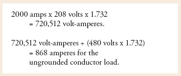
Formula 9
The load on the grounded (neutral) conductor for the feeder now rated at 480Y / 277 volts is:
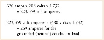
Formula 10
In accordance with Table 310.16, 700 kcmil copper conductors paralleled twice (460 amperes x 2 = 920 amperes) are the minimum size required to serve the load. However, per 240.6, the next standard size overcurrent protective device size above 868 amperes is 1000 amperes, and the conductors are required to be sized per the overcurrent device size at a minimum. Table 310.16 indicates that 900 kcmil THWN copper conductors paralleled two times = 1,040 amps, and would be code-compliant for the installation; but with the long distance of the feeder, we must verify that all conductors are sized large enough to be code-compliant and properly sized to serve the load, including the grounded (neutral) conductor. The minimum size grounded (neutral) conductors sized per 310.4 as a minimum 1/0 copper (installed in parallel in each non-metallic raceway) = (150 amperes x 2 = 300 amperes), which under normal conditions would meet the requirements for the 269 amperes capacity for the conductors. The minimum size EGC—again required to be installed in each paralleled non-metallic raceway—per 250.122(F) must be verified for proper sizing. Generally, the minimum size EGC for a 1000 ampere feeder per Table 250.122 is 2/0 copper.
The calculation for the ungrounded conductors is as follows:

Formula 11
Because of the requirements of 240.6, the ungrounded conductors were increased in size from 700 kcmil to 900 kcmil copper. This is a 29% increase in size, and the grounded (neutral) conductors and equipment grounding conductors must be increased by the same proportion, per 250.122(B). For the 1500-foot distance of the feeder, because the voltage is higher at 480 volts (as opposed to 208 volts), the amperage of the load is less.
The minimum size grounded (neutral) conductor permitted to be installed in parallel is 1/0, in accordance with NEC 310.4. Each grounded conductor must be increased 29% to account for voltage drop, the same as all other conductors of this feeder. A 1/0 copper conductor = 105,600 cm x 1.29 (129%) = 136,224 cm. Based on chapter 9, Table 8, Conductor Properties, 136,224 cm is not a standard size conductor. From this table, you will find that the next larger size found is 3/0, which is 167,800 cm in size. A 3/0 copper grounded (neutral) conductor is then required to be installed in each of the two paralleled non-metallic raceways for this feeder.
The calculation for the grounded conductor is:

Formula 12
The minimum size EGC for a 1000-amp feeder is 2/0 copper, which must be increased in size by a minimum of 29%. The question is, How many circular mils (cm) in size is a 2/0 copper conductor? The answer is found in chapter 9, Table 8, Conductor Properties. From this table, find that a 2/0 conductor is 133,100 cm in size. 133,100 cm x 1.29 (129%) = 171,699 circular mils. This is not a standard size conductor. Note that the next higher and closest size is a 4/0 conductor, sized at 211,600 cm (circular mils). A 4/0 copper EGC is required to be installed in each of the two paralleled non-metallic raceways for this feeder.
Figure 2. The same feeder as figure 1, except now at 480Y/277V with step up and step down transformers to account for voltage drop
Once again, it is important to remember that the Code is not a design or specification manual, but it is a minimum standard for electrical installations.
In this article, we have discussed the voltage-drop requirements found in the NEC, illustrated the use of a formula for determining the amount of voltage drop on a long feeder or branch circuit, some items to consider when designing electrical installations that include the termination of long runs of conductors, and the proper sizing of equipment grounding conductors for installations where voltage drop is a factor.
Electrical installations must meet at least the minimum requirements of the Code. While the FPN following Section 210.19(B) and FPN No. 2 to 215.2(3) are explanatory material and not mandatory, 110.3(B) is definitely one of the requirements which cannot be ignored, and does apply relating to the voltage drop of conductors that supply utilization equipment.