Electrical calculations generally fall within two categories: dc circuit analysis and ac circuit analysis. In a typical engineering curriculum dc circuit analysis is introduced first with resistive networks. Once all the network theorems are discussed and evaluated, ac circuit analysis is introduced. AC circuit analysis is more complex and requires the use of calculus if the circuits are evaluated in the time domain. Usually the concepts of inductive reactance, capacitive reactance, and impedance simplify the circuit analysis in the frequency domain. To allow for this simplification in the frequency domain the following criteria must be met: voltage and current sources must be sinusoidal in nature, and complex impedance must be expressed either in polar or rectangular notation. Vector analysis is also very helpful as it allows for a graphical presentation of circuit characteristics. AC circuit analysis is further broken down into single-phase and three-phase applications. The same network theorems that are used to evaluate resistive networks in dc circuit analysis can also be used to evaluate ac circuits that include resistors, inductors, and capacitors.
Illustrated here are five example calculations. Examples 1 and 2 are dc circuit calculations involving resistors. Examples 3 and 4 are ac circuit calculations involving inductors. Example 5 is a voltage-drop calculation. Please note that the ac circuit calculations will contain only the magnitude and not the phase angle of the answer to keep things simple.
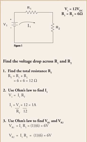
Example 1 is a dc circuit with a 12-V source and two series connected resistors R1and R2. Since it is a series circuit, you should note that the current I1will be the same through each resistor Also note that the algebraic sum of the voltage drops should equal the voltage rise. The first step is to calculate the total resistance RT. The next step is to use Ohm’s Law to calculate the current I1. The final step is to use Ohm’s Law again to solve for the voltage drop VR1across resistor R1, and the voltage drop VR2across resistor R2. You will note in the final answers that the voltage drop VR1is 6V, and the voltage drop VR2is 6V. KVL is maintained as the algebraic sum of the voltage drops 6V + 6V equals the voltage rise V1of 12V.
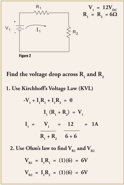
Example 2is the same dc resistive circuit, only this time we will solve for the voltage drops using Kirchhoff’s Voltage Law (KVL). In this example we write one mesh equation around the loop in a clockwise direction, following the assumed direction of current flow for I1. This mesh equation is -V1+ (I1)(R1) + (I1)(R2) = 0. Algebraically solving for I1, we find the current. The final step is to use Ohm’s Law to solve for the voltage drop VR1across resistor R1, and the voltage drop VR2across resistor R2.
Example 2
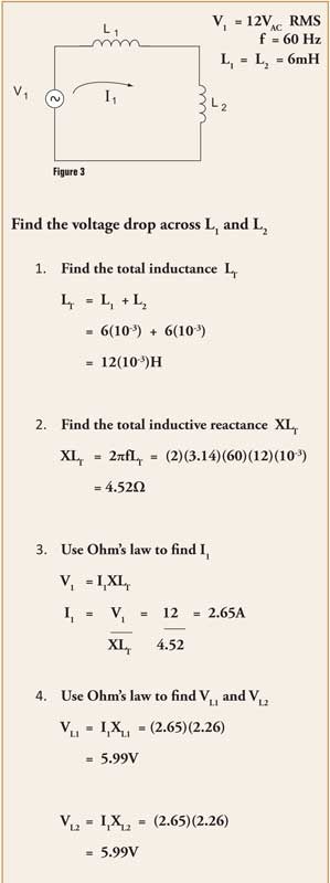
Example 3 is an AC circuit with a 12V RMS source and two series connected air core inductors L1and L2. The first step is to calculate the total inductance LT. The next step is to calculate the total inductive reactance XLTat the specified frequency of 60 Hz. The next step is to use Ohm’s Law to calculate the current I1. The final step is to use Ohm’s Law to solve for the voltage drop VL1across inductor L1, and the voltage drop VL2across inductor L2.
Example 3
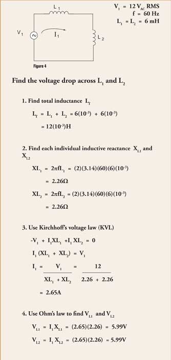
Example 4 is the same ac circuit, only this time we will solve for the voltage drops using Kirchhoff’s Voltage Law (KVL). In this example we write one mesh equation around the loop in a clockwise direction, following the assumed direction of current flow for I1. The mesh equation is -V1+ (I1)(XL1) + (I1)(XL2) = 0. Algebraically solving for I1, we find the current. The final step is to use Ohm’s Law to solve for the voltage drop VL1across inductor L1, and voltage drop VL2across inductor L2.
Example 4
Example 5 is a voltage drop calculation with a 120V RMS source and a 1200W resistive load. The first step is to calculate the current I1. Since this is a resistive load the power factor will be unity or 100%. The next step is to calculate what voltage will be dropped across the conductor as it delivers current to the load. The final step is to calculate the cross-sectional area of the conductor at the specified length of 150 ft.Ohm’s Law and Kirchhoff’s Voltage Law are very useful in circuit analysis. The simple examples given here should illustrate the basic calculation methods that are used to solve for various circuit parameters.
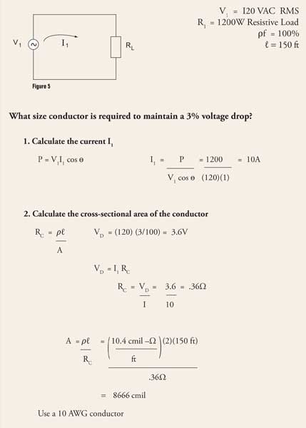
Example5


Find Us on Socials