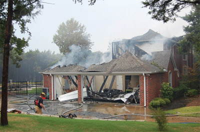
 Electrical faults are responsible for a substantial number of residential structure fires that result in almost $1B in personal losses, thousands of injuries and hundreds of deaths each year. With the latest circuit breaker technology, many of these fires would never have ignited. However, many ignition mechanisms can only be prevented by outlet-based technologies.
According to expert knowledge documented in NFPA 921,Guide for Fire and Explosion Investigations, electricity ignites fires from two primary heat causes: arcing and resistive heating faults. If fault detection occurs before flammables ignite, a pending fire can be prevented by interrupting the current. Thus circuit interrupter technologies can often prevent these fires if they can detect the symptoms and trip.

Photo 1. High resistance, arcing or glowing connections can eventually lead to ignition. Courtesy of 2D2C, Inc
At a more detailed level, NFPA 921 describes specific ignition causes. Table 1 summarizes this information and categorizes it into arcing and thermal categories and specific cause sub-categories. Note that presently neither the U.S.National Electrical Code(NEC) nor the Canadian Electrical Code (CEC) require protection from these highlighted resistive-heating ignition causes.
For fire prevention, bothNECand CEC presently require use of arc-fault circuit-interrupter (AFCI) and overcurrent protection in circuit breakers. UL 1699 Standard defines AFCIs intended for use in dwelling units. UL 489 Standard defines the construction, performance, tests, ratings, and markings for most other types of branch-circuit breakers including overload, instantaneous trip and ground-fault protection.

Table 1. Specific ignition causes described by NFPA 921, Guide for Fire and Explosion Investigations. Courtesy of 2D2C, Inc
AFCI devices are intended to mitigate the effects of both series parting arc and parallel arc faults that may pose a risk of fire ignition under certain conditions if the arcing persists. However, electrical fires can still start on a circuit protected by an AFCI. AFCIs are not intended to detect resistive heating faults other than branch-circuit overcurrent. Furthermore, UL 1699 does not require detection of parting (series) arcs below 5 A current, likely to minimize false tripping by motors, switches, relays, fire alarm communication signals, and switching power supplies.
Installation of AFCIs on branch circuits should reduce the number of arcing-ignited fires. The Electrical Safety Authority (ESA) in Ontario, Canada, documents the forensic work of the Ontario Fire Marshal’s office regarding electrical ignitions in large fires. The 2008 ESA report (see table 2) suggests that 29% of the electrical fires from 2002 to 2007 were caused by Arcing and 40% from Resistive Heating. In 19% of the fires, evidence was unclear or destroyed (categorized as “Unknown”). In 12% of the fires, ignition occurred directly (e.g., cardboard box left next to electric heater). Ignoring “Direct” ignition and weighting the “Unknown” cause fires, we could extrapolate arcing to cause 42% of preventable electrical fire ignitions, and resistive heating to cause 58% of all technology-preventable ignitions.

Table 2. Electrical Ignition Causes, Major Fires 2002–2007 Courtesy of 2D2C, Inc
Table 3 from ESA further provides insight into exactly what types of resistive-heating faults are igniting most of the structure fires. Of the ignitions from resistive heating, Poor Connections cause 34% and Overloaded Equipment cause 30%. AFCIs are not designed to prevent ignitions from resistive heating at bad wire terminations (poor connections) and in appliance wiring (overloaded equipment). They are designed to trip on arcing in wire terminationss and in appliance wiring (> 5A). Thus, additional protection is needed.
Virtually all premise electrical distribution systems have fuse or circuit breaker protection to limit heat build-up in branch circuit wiring. The inherent resistance of wires and connections results in heating with the flow of electricity. Properly sized and installed wiring, in conjunction with overcurrent protection in the form of fuses or circuit breakers, limits the heat build-up to safe levels. Circuit breakers and fuses have trip characteristics designed to protect properly sized, installed and maintained wiring system components, but not all the small gauge wires found in many appliances.
In spite of circuit fuses or breakers, many fires still ignite from electrical faults. Clearly, fuses and circuit breakers alone are not a complete solution. Overheating of properly installed and maintained wiring systems is not the only cause of electrical fires.

Table 3. Resistive-Heating Ignition Causes, Major Fires 2002–2007. Courtesy of 2D2C, Inc
For many of these ignition causes, good protective technology and standards exist. New circuit breaker and receptacle outlet technologies can protect against many of the common low-voltage ignition causes. Lightning rods, spark gaps, surge protective devices (SPD) and high voltage wiring standards help prevent fires from high voltage surges and arcs.
Circuit Breakers
Standard circuit breakers perform well to protect against short circuits and associated sparks, plus overloads in premise wiring. For short circuits (see NFPA 921, section 8.11.9) and high resistance faults (see NFPA 921, section 8.9.6), a current sensing magnetic trip disconnects the feed current rapidly, in less than a second. For overloads in premise wiring (see NFPA 921, section 8.9.3), circuit breakers trip in seconds to minutes by sensing heat build up in an internal chamber. The circuit breaker trips more quickly on larger overloads to protect the premise wiring insulation from damage and to prevent ignition.
Since the overload condition can be caused by a temporary excessive utilization load, circuit breakers can be reset by the resident after the overload condition has been cleared. However, in the author’s opinion, fire investigators would be better served if a permanent flag was set on each circuit breaker after it tripped to assist with post-fire forensic investigation.

Photo 2. Heat releases carbon molecules in organic materials. Browning or blackening of plastics indicate advanced pyrolization and high ignition potential. Courtesy of 2D2C, Inc
Arc-Fault Circuit Interrupter (AFCI)
In recent years, arc-fault circuit interrupter (AFCI) circuit breakers have been introduced to the market to prevent fires from arcing between wires. The first AFCI breakers were called “branch/feeder” type (USA) or “breaker” type (Canada). Branch circuit/feeder AFCI devices detect series arcing events at 80-85 amperes. Combination AFCI devices detect series arching events at 5 amperes. Because of this fact, branch circuit/feeder AFCIs did a much better job of detecting parallel arcing events than they did detecting a series arching event. UL 1699 Standard for AFCIs assumed that most fires from parallel arcing resulted from cracked insulation, line surges and resultant arc tracking. These interrupters were an improvement compared to overcurrent circuit breakers, but could not detect many arcing conditions that lead to fires.
New AFCIs, “combination,” introduced late in 2007, now detect both series arcing (unintentional parting arcs) and parallel arcing. AFCI series arc detectors are designed to trip on arcs in-line with the circuit path (i.e., a loose wire connection) if greater than 5 amperes. Series arcing is a serious issue with fires directly associated with aluminum wiring where the energy associated with the arcing can be adequate to melt the aluminum and throw sparks (see NFPA 921, section 8.9.5). Series arcing can also pit and oxidize brass and steel contact points and lead to a high-resistance connection (see NFPA 921, section 8.9.2.3) of wires or contacts. High current flowing through a high-impedance connection is a leading cause of electrical fires.

Figure 1. OPCI-V is an electronic circuit that measures the line voltage, compares it against safe limits, and disconnects the load when abnormal conditions are detected. Courtesy of 2D2C, Inc
For the USA, UL Standard 1699 defines AFCI testing, performance and safety requirements for NRTL listings. For Canada, CSA uses Technical Information Letter No. M-02A (a full standard has been drafted, but not yet published) for interim certification of arc-fault circuit interrupters and arc-fault protection devices.
UL 1699 tests for AFCIs include both series and parallel arcing conditions. Series tests force parting arcs at 5 amps and above across a copper to carbon interface. Parallel tests create a parallel carbon conduction path of arc tracking by exposing damaged wires to 7.5 kV. These tests create a fairly consistent method for testing AFCI breakers, but do not necessarily represent realistic conditions. For example, series arcing from a copper rod to a carbon rod, as required by UL 1699, creates a sustainable arcing condition. Most residential branch circuits use copper wire only. Connections are copper to copper or copper to brass/steel. Series arcing from copper to copper (e.g., two wires under a wire nut) or from copper to zinc-coated steel (a wire screwed to a receptacle) self extinguishes quickly and is more difficult to detect consistently.

Figure 2. The performance of AWG 14, TW 60° C cable falls within the protection specifications of a 15-A circuit breaker. Courtesy of 2D2C, Inc
Note, if an AFCI trips on a parallel arc fault, wire insulation damage has likely occurred. A crack in the insulation along with a carbonized arc tracking path between line and ground may exist. The UL 1699 test simulates these conditions using a slit in the wire insulation between the conductors plus application of high voltage to create an arc track path to ground. In the author’s opinion, if the AFCI device trips on a parallel arc, the AFCI device should not be resettable in this situation, since a pending fire ignition situation still exists. In contrast, if an AFCI trips on a series arc fault, the cause may have been a temporary contact-parting condition. In either case, an electrician should service the facility anytime an AFCI protective device trips to repair the fault condition.
AFCIs detect and protect against multiple arcing fault conditions, but cannot correct them.
AFCIs are available from all the major suppliers of circuit breakers.
Out of Parameter Circuit Interrupter – Voltage type
An out of voltage parameter circuit interrupter (OPCI-V) can detect and protect against electrical hazards that lead to ignition including abnormal line voltage, open neutral faults, high-resistance connections, and damaged wiring. OPCI-V provides good protection against fires caused by abnormal line voltage across a load device, frequently caused by an open neutral connection and occasionally caused by electrical utility regulation problems. OPCI-V provides reasonable protection against high-impedance connections and damaged wires, and good protection against voltage fluctuations that typically occur immediately before and after a blackout. In order to protect against both overheating high-impedance connections and “open neutral” faults, OPCI-V must be located in an electrical outlet, downstream of the fault location and in series with the load.

Figure 3. Wire damage can occur without the circuit breaker tripping when current exists between 12 A and 15 A for long durations. Courtesy of 2D2C, Inc
Power faults include both abnormally high and low line voltage conditions. High line voltages can stress appliances and lead to ignitions, or simply destroy electronic devices, computers, electrical equipment and light bulbs without causing a fire. Low line voltages can stress switching power supplies and relays (“hold chatter”) leading to improper operation or outright destruction. Relay chatter can cause contact pitting, high-resistance contacts, overheating, and ignition. Power failures are frequently preceded by wild voltage fluctuations, and during recovery the power can cycle on and off numerous times. Rapid power cycling is well known as a cause of stress and damage to sensitive electronic equipment.
OPCI-V is an electronic circuit that measures the line voltage, compares it against safe limits, and disconnects the load when abnormal conditions are detected. ANSI C84.1 Table 1 documents the normal service voltage range at receptacles to be 106 Vac to 127 Vac. However, experience tells us that voltages slightly above this range are occasionally experienced in rural areas. The OPCI-V upper voltage limit, at 130 Vac, has been selected to provide protection against hazardous abnormal voltages while minimizing the possibility of nuisance tripping. OPCI-V continuously monitors for violations of these limits (below 106 Vac and above 130 Vac).
OPCI-V built into an electrical outlet includes the following components:
- AC voltmeter
- Comparison circuit
- Timer circuit
- At least one high-current relay controlled by the comparison and timer circuits
- Status indicators

Figure 4. 15-A circuit breakers cannot adequately protect 18 AWG when passing maximum current rating for long durations. Courtesy of 2D2C, Inc
- The comparison circuit continuously checks the line voltage against the OPCI-V upper and lower limits. If the line voltage goes outside the limits, the OPCI-V disconnects the load(s).
How does OPCI-V protect from high resistance connections?
Current flowing through a high resistance creates a voltage drop across the connection. For example, 10 amps through a 3-ohm connection drop 30 volts across the connection. The voltage drop can cause the line voltage at the OPCI-V outlet to be less than 106 Vac, its lower trip threshold. The OPCI-V outlet disconnects the load when the voltage drop is detected. By disconnecting the load and stopping current through the high resistance connection, heating and risk of fire is effectively mitigated.
How does OPCI-V protect from “open neutral” conditions?
When a high-resistance connection or open circuit exists in the neutral return conductor of a split phase service the voltage balance between the two circuit legs is disturbed. OPCI-V detects either a low voltage or high voltage condition depending on which circuit leg it is connected to. Upon detecting line voltage outside acceptable limits (106 V to 130 V) the load is disconnected from the supply. After the imbalance is rectified, OPCI-V reconnects power to its loads. Preventing a high voltage condition across high resistance loads is especially important, since these loads usually contain thin wires (e.g., 20, 22, 28 gauge wire) that will quickly overheat from the higher current and drastically increase the risk of fire.
OPCI-V detects and protects against multiple fault conditions, but cannot correct them.

Figure 5. Wires that are 20 AWG or smaller need additional protection beyond a 120-Vac, 15-A branch circuit breaker. Courtesy of 2D2C, Inc
CSA International has developed a draft new standard C22.2 No. 265 for 120-Vac, 60-Hz Out of Voltage Parameter Circuit Interrupter (OPCI-V) outlets.
The first commercially available products that contain OPCI-V are the SafePlug Model 1200 and Model 1300 series duplex-receptacle outlets.
Out of Parameter Circuit Interrupter (OPCI-I) – Current type
Circuit breakers do not have the sensitivity to detect overheating of smaller gauge electrical device wiring than the gauge of branch wiring they were designed to protect. Smaller gauge wires in extension cords and appliances can overload and overheat without the circuit breaker tripping. OPCI-I circuitry is designed to protect against overload conditions in appliance wiring.
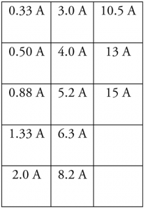
Effectively, an OPCI-I is a variable threshold, re-settable, electronic circuit breaker located inside each electrical receptacle. The trip threshold automatically adjusts to matches the electrical rating of the load device plugged into the receptacle. Available OPCI-I products have thirteen different rating levels ranging from 1/3 amp to 15 amps (on a 15-amp circuit).
In order to properly protect connected utilization equipment, OPCI-I must be located in the outlet where the smaller gauge appliance wiring connects to the electrical system and/or in the appliance itself. Smaller gauge wiring found in most appliances and electrical extension cords can overload, overheat and suffer long-term damage at current levels below the 15-A rating of the smallest branch circuit breaker.

Figure 6. OPCI-I built into an electrical receptacle automatically configures its trip level to match the electrical ranting of each electrical device plugged into that receptacle. Courtesy of 2D2C, Inc
Excess current creates heat. Heat above 70 degrees C (158° F) degrades the flexibility and insulating properties of most PVC electrical insulation. Eventually the heat causes chemical break-down of the insulation that releases conductive carbon. The lowered resistance of the carbonized insulation can trigger arc tracking and ultimately ignite fires. Although an AFCI will trip when sufficiently severe arc tracking occurs, an OPCI-I can prevent the damage to the insulation that leads to the arcing by tripping immediately after the appliance overload occurs.
For example, the performance of AWG 14, TW 60° C cable falls within the protection specifications of a 15-A circuit breaker is shown in figure 2. The grayed out area shows the tolerance range for tripping on excess current and duration, as defined by UL 489 Standard. The vertical gray section is the range for the instantaneous trip function (> 100 A) and curved gray section (> 1 s duration) is the range for the thermal detection for current limiting. See that the circuit breaker will always trip before conditions reach a damage point for AWG 14 wire.
In this second example of a 15-A circuit breaker and 16 AWG TW 60C (figure 3), the circuit breaker provides adequate protection in most conditions. However, wire damage can occur without the circuit breaker tripping when current exists between 12 A and 15 A for long durations. Most household extension cords contain 16 AWG wires. Although a 16 AWG cord should not be used for a 12-A load, consumers make this mistake. In this situation, OPCI-I can prevent insulation carbonization and eventually arc tracking and ignition conditions.
Fifteen-amp circuit breakers cannot adequately protect 18 AWG when passing maximum current rating for long durations (see figure 4). Again, OPCI-I is needed to prevent damage and ignition.
Finally, any wires that are 20 AWG or smaller need additional protection beyond a 120-Vac, 15-A branch circuit breaker (see figure 5).
Although this protection could exist in the form of a fuse in the appliance and required by new appliance standards, a number of reasons exist that make this approach less effective and impractical.
Many appliance standards would need to be changed instead of just one NEC change.
Appliance manufacturers will strongly resist more appliance safety requirements due to the additional manufacturing cost.
New appliances standards will not prevent fire ignitions from the billions of existing appliances, whereas OPCI-I will protect both new and old appliances.
Appliance manufacturers will set fuse trip levels as high as possible to avoid customer support burdens upon manufacturers.
This last point is substantiated by recent market behavior. An actual fan manufacturer’s response to a threatened government recall of their product was to install a fuse in the cord. Rather than setting the fuse size to prevent product damage, it was set to never blow. Normal current was 1 A, the locked rotor current was 1.7 A and the fuse was selected to blow at 3 A. Tests showed that the motor would melt and smoke, and occasionally ignite at just under 3 A. The manufacturer chose this level to avoid excessive customer support calls as the motor bearings collected dust and wore out.
OPCI-I also provides protection for high line voltage or “open neutral” conditions by detecting the resulting excess current flow.
In my opinion, OPCI-I should be required by NEC to be incorporated into 120-Vac, 15-A and 20-A electrical receptacles for fire prevention. OPCI-I built into an electrical receptacle includes the following components:
- One ammeter for each receptacle
- Comparator circuit
- One high-current relay for each receptacle controlled by the comparator circuit
- Plug tag reader to identify OPCI-I level for the appliance plugged in
- A power supply
- Status indicators (not required by CSA 22.2 No. 265 draft std)
The ammeter measures the current drawn by the electric load plugged into the receptacle. When the comparison circuit detects load current in excess of the device rating, it opens the relay disconnecting the load. The actual trip limit is slightly higher than the maximum operating current of a device (called the “hold level”), but is much lower than the trip level of a similarly sized circuit breaker or fuse. For child shock protection, the relay is normally open to keep electricity off at an empty receptacle socket.
A block diagram of an OPCI-I electrical outlet with an appliance plugged in is as shown in figure 6. In this example, the appliance plug tags use proprietary standard RFID tags and the OPCI-I contains a proprietary tag reader to prevent counterfeiting. The tags were developed to contain both appliance safety information and Smart Grid address identification.
OPCI-I built into an electrical outlet automatically configures its trip level to match the electrical rating of each electrical device plugged into that receptacle. When an electrical device plug is inserted into an OPCI-I receptacle, the OPCI-I reads the electrical rating information from the proprietary compliant tag embedded in the plug. The tag acts somewhat like a wireless memory stick, the memory contains safety information about the load device, such as its current rating.
The manufacturer’s standard defines a means of storing normal current draw for appliances. For 15-A plug loads, 13 different safe limits (hold-current levels) for OPCI-I tripping exist to closely match the power rating of the appliance:
Once the OPCI-I reads the tag, the OPCI-I sets its maximum hold current to match the level read from the tag and closes the power relay to deliver electricity to the receptacle. It continuously reads the tag to determine if the plug has been removed or if a different device plug has been inserted in the receptacle.