In the last issue we ended with the requirements for underground installations in 300.5. We’ll pick up where we left off with 300.6, Protection against Corrosion and Deterioration. The basic requirement is that equipment must be suitable for the environment in which it is installed.
Take a look at this section in your code book and you will find a long list of items to be considered related to damage caused by the environment in which electrical equipment is installed. The first item in the list is Ferrous Metal Equipment, which is metal containing an appreciable amount of iron. Since it is sometimes difficult to tell what metal was used just by looking, you can test the metal with a magnet. If the magnet is attracted to the metal, it is a ferrous metal. The NEC states that these materials shall be suitably protected by a coating of an approved corrosion-resistant material; this is commonly achieved by galvanizing during the manufacture of the product. The code also states that for field threaded conduit, you must take the required steps to maintain the corrosion protection while keeping the conductive properties of the conduit. Please review 300.6(A), where you will find additional information regarding different types of protection in (1) through (3). Please also be familiar with your local conditions. Here in southern Nevada, we have very corrosive soil that attacks raceways installed underground, so we’ve had to address some of these conditions with local amendments.
In 300.6(B) through (D) the protection of Aluminum Metal Equipment, Nonmetallic Equipment and Indoor Wet Locations are addressed. A couple of comments are appropriate here regarding nonmetallic systems; if they are exposed to sunlight they need to be listed for such exposure, and if exposed to chemicals they need to be resistant to the hazard. Regarding corrosive locations, there are two common types that come to mind. The first would be a wet battery service location where they are repairing and charging batteries; here you have a heavy concentration of acidic fumes which can quickly destroy metallic raceways. The second is in pool equipment rooms where the equipment is exposed to the fumes of both acid and chlorine concentrations. In both of these locations, I’ve found the preferred method is the use of nonmetallic materials as they will generally outlast metallic equipment. Metallic equipment at times will not last more than a year in such environments, depending on the concentration of the exposure. Lastly, we cover indoor wet locations, which has a simple rule that the entire wiring system (where installed exposed) shall be spaced a ¼″ off the surface. This allows an air space behind the equipment to allow drainage and to prevent a buildup of materials which may cause damage to the equipment.
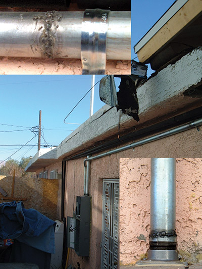
Photo 1. Art 300.18(B) clearly states that raceways shall not be welded unless designed to be welded, here we have an installation that has welded joints as can be seen by the insets.
Raceways Exposed to Different Temperatures are covered in 300.7; this is a simple requirement, yet often missed in the inspection process. One of the most common occurrences where this applies is where we have wiring methods being installed into the interior of a freezer or cold storage location. The difference in temperature will cause condensation within the raceways and equipment; and if we don’t seal these as close as possible to the actual penetration point of the raceway, we will create a hazard. I’ve seen light fixtures inside coolers that have been filled with water as a result of ignoring this requirement, and water and electricity just don’t make a good match. I’ve seen some of the lights continue to operate, even though the lamps are submerged in water. Note that the required method of sealing the raceways or sleeves doesn’t have to be an explosionproof seal off, we just need to seal the raceway with an approved material that will fill the space. The material used should be intended and identified for use with electrical cables and equipment.
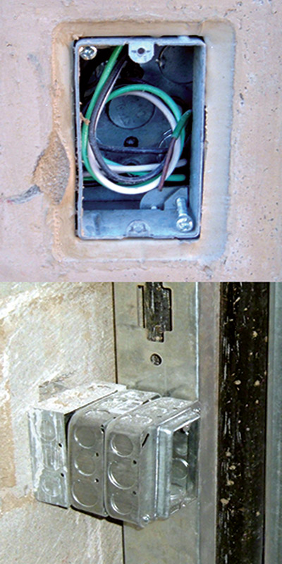
Photo 2. In the top photo the electricians have done a good job with making sure they have the proper length of free conductors, as noted on 300.14. In the lower photo you can see how adding extension boxes may be added and the code still would require 3 inches of free conductor outside the last extension.
Also in this section we cover Expansion Fittings. Raceways must be provided with these fittings where necessary to allow for expansion and contraction. One of the common locations for this issue is in larger buildings that have building separation expansion locations. Usually this is accomplished by the installation of a flexible raceway system installed at this location with a bit of slack to compensate for any movement. There are listed expansion fittings available. Use a bit of caution here: if using a listed fitting, make sure it is compatible with the raceway systems being installed.
Next we will skip to 300.10, Electrical Continuity of Metal Raceways and Enclosures. When using metallic wiring methods, they shall be metallically joined together into a continuous conductor and shall be connected to all boxes, fittings and cabinets to provide electrical continuity. The issue here is that we are often using the metal raceway system as our grounding path. Even if we are not, it still has the possibility of becoming energized and we must therefore ensure we have a good low-resistance path back to the location of the overcurrent device to insure it will operate in a timely fashion if needed.
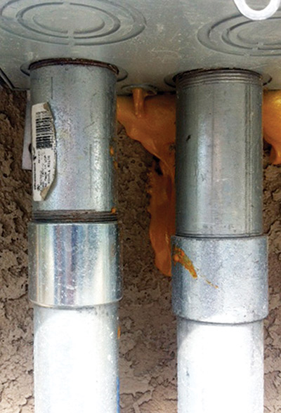
Photo 3. In this photo we find a lack of lock nuts under the enclosure. In 300.10 the code requires raceways to connected to all boxes to provide for electrical continuity. In order to do this, we require lock nuts on both sides of an enclosure.
Securing and Supporting requirements are found in 300.11. In (A) we cover Secured in Place and find that raceways, cables assemblies, boxes, cabinets and fittings must be securely fastened in place. The code then goes into detail for installations done within ceiling assemblies; generally, the requirement here is that electricians need to install independent support wires for the electrical installations, which need to be supported at both ends of the support wires. It is further noted in the fire-rated and non-fire-rated installations that these support wires must be identified in order to show that the wires utilized for the support of our systems are independent of those installed to support the ceiling assembly. This identification can be done using one of several different methods, whichever is acceptable to the authority having jurisdiction. Locally, the simplest method we found was using the products specifically made to secure the support wires to the ceiling grid. That insured no additional stress was added to the ceiling system, and the products are made in a unique color which easily allows identification during the inspection process. Instead of covering 300.11(B) Raceways Used as Means of Support, I will state a general rule of thumb: raceways are not allowed to support other raceways. Please read this section as there are some applications that are permitted; however, I haven’t seen a system that allows raceways to support raceways. If you see an installation like this, ask questions until you are satisfied that the installation is properly done.
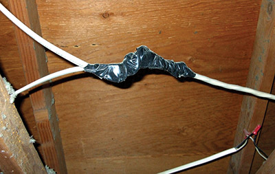
Photo 4. Article 300.15 requires boxes to be used for conductor splices when utilizing nonmetallic-sheathed cable; as you can see in the above photo, not everyone knows the code or follows it.
Next, we’ll group 300.12 and 300.13 into some simple language. First, raceway systems shall be continuous, which means no breaks between cabinets, boxes fittings or other enclosures or outlets. Second, the installed conductors shall not be spliced within a raceway, unless permitted in the areas of the code specifically listed in 300.13(A). Also covered here is the continuity of the grounded or neutral conductor of multiwire branch circuits; this is where we are sharing a neutral for more than one ungrounded conductor, which is permitted as long as the ungrounded conductors are on different phases. If we have these conditions, then we must make sure the neutral is continuous even if we take out a receptacle or other device. We do this by connecting the neutrals together with a twist-on wire connector and provide a short pigtail for connection to the receptacle. When we do this, if the receptacle is removed the neutral is still continuous and the circuit is complete; if we don’t do this, then when we interrupt the neutral or open it, the devices downstream from this location may see the potential between the other phase conductors, which is the phase-to-phase voltage of the system. This simple mistake will destroy equipment and also create a shock hazard if the other conductors of the multiwire circuit aren’t disconnected.
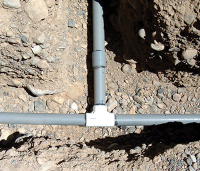
Photo 5. This photo shows an electrical installation that has had the conductors threaded through the raceways. Article 300.18 requires the raceways to be complete prior to conductor installation. The feed is from the left and the load is to the right, the top run goes to the disconnecting device, so we have both line and load in that run. The homeowners who did this installation put in a considerable amount of labor and injuries to get it this far; however, once we failed the inspection I think it might have led to other issues for the homeowners.
Length of Free Conductors at Outlets, Junctions, and Switch Points is covered in 300.14. This is a very important part of the code that needs to be checked during the rough inspection. As mentioned in previous articles, during the rough inspection we have to verify that we have proper make up and identification within each box for both the grounded and grounding conductors. The other thing we should be checking at the same time is the amount of free conductor; too little and it is very difficult to make the proper connections to the wiring devices being utilized. If we have too much free conductor, then we have a space issue when we try to push the device back into the box, which may lead to damaged conductors and a hazardous condition due to nicked insulation. The code is very clear on this subject: where we have a box that is less than 8 inches in any dimension, the amount of free conductor required is 6 inches from where the conductors emerge from the raceway or cable sheath. However, we don’t just stop with that, it also has to have 3 inches of free conductor past the face of the box, which is enough conductor for those situations where we might have to utilize deep boxes or extension boxes. With some of the devices, such as GFCIs, AFCIs, dimmers and occupancy sensors, the free area inside the box may become scarce. If you have locations where you know you may use a large device, be on the lookout and mention it to the electrician; you may just be saving him some trouble during the trim out process. Further into Chapter 3 we will cover the size of the box related to the size of device, but we will not be tempted to look ahead just yet.
The requirements for boxes, conduit bodies, or fittings are covered in 300.15. A box shall be installed at each conductor splice point, outlet point, switch point, junction point, termination point, or pull point unless not required in the 300.15(A) through (L). These twelve exceptions deal with specific types of wiring methods or products that have unique conditions which would not require a box; please review them to see what these conditions are, as I am not going to mention each of them here. Even though there are several exceptions, this is actually a pretty simple rule. Please review 300.16 for more information related to the use of boxes, conduit bodies or fittings.
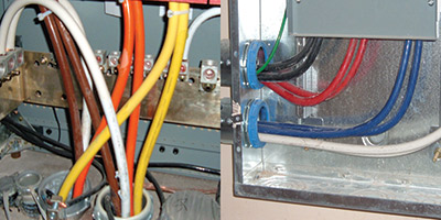
Photo 6. These photos show conductor phase arrangements. Both are in metallic raceways, so the left photo shows a code compliant installation as per 300.20. In each run we have each phase, grounded and grounding conductor grouped in each raceway. In the photo to the right, we have a code violation.
I’m not going to cover 300.17 Number and Size of Conductors in Raceways, due to the fact that we will cover it in much more detail when we get to Article 310.
Skipping ahead to 300.18 Raceway Installations, this section is broken down into two parts. First, in (A) we have Complete Runs, and the requirement here is that raceways, other than busways, or exposed raceways having hinged covers, shall be installed as a complete run between outlet, junction, or splicing points prior to the installation of conductors. If you ever get on site and see someone threading conductors through pieces of raceway, please remember this section of the code. If the conductors can’t be pulled through a completed raceway installation, there is another problem which should be solved. Examples might be oversized conductors in the raceway, too many bends in the run, or other conditions that shouldn’t exist in a good code-compliant installation. The second section of 300.18 deals with Welding. Metal raceways shall not be supported, terminated or connected using a welding process unless specifically designed for welding. To date, I haven’t seen a system designed to be welded. However, that doesn’t mean I haven’t seen it attempted, as can be seen in one of the photos with this article. It should be pretty obvious that welding would cause rough, possibly sharp obstructions to the interior of the raceway, which would then cause damage to the conductors when they are being installed within the raceway system.
In vertical runs of raceways, we have to address the need to support the conductors from the pull of gravity. If you have a vertical run of 300 feet (approximately 30 stories) and you have four 500 kcmil copper conductors, the weight would be close to 1800 pounds. If these were simply terminated into the set screw lugs of a panelboard on the thirtieth floor with 1800 pounds of pressure pulling down, the panel would be destroyed. So how do we compensate for this? In 300.19, the code addresses how to support the conductors. First, we are to have a support at or as near as possible to the top of the raceway. Then, according to the size and type of conductors as noted in Table 300.19(A), we are required to add additional supports at certain distances. For our simple example above, we would need supporting points every 40 feet, or once every 4 floors. Please open your code book and read 300.19(C) for the options and alternate methods that can be used.
The last item I’m going to cover in Article 300 is 300.20 Induced Currents in Ferrous Metals Enclosures or Ferrous Metal Raceways. When installing alternating-current circuits in ferrous metal raceways or enclosures, you have the possibility of creating heat in the raceways through induction. To minimize this, the code requires that we group each of the phase conductors and the related grounded (neutral), and grounding conductor in each raceway. This will allow for cancellation of the magnetic fields created due to the nature of the alternating current in the conductors. If we don’t address this, we can have overheating of the conductors.
In 300.20(B), we have the method for installing Individual Conductors. The most common installation of this is mineral-insulated cables, which in larger sizes are one conductor per cable. When we have this type of installation, we are required to cut a slot between each cable connector when entering an enclosure, or to use an insulated wall properly sized for all the conductors. I have never seen the insulating wall option applied, so we generally see a slot cut between the connectors. This slot is nothing more than a saw blade width but remember that if entering an outdoor enclosure, doing this might compromise the outdoor rating of the enclosure.
Again, please take the time to open your code book and review the rest of Article 300. I have only touched on the most common areas which are used in various combination inspections. In the next article, we will start into Article 310, which is where we get into details on conductors.





Find Us on Socials